background image


◆ 

When the cursor is on New Task, press            /            to create a new task with the last one as a template.


 Press          /          to select a task and view its information, and press      /     to page up and down.


 Press             to save as a new task.


 Press             to delete the selected task and its data. Carefully select your operation as it cannot be reversed.


 If the selected task calibration has not been ran, press             /            to show the run information screen.


 If the selected task has been ran, press            /           to view the report. 


 The task can be repeated, but only the last result will be recorded. Carefully select your operation as they cannot be 

            reversed.


 View the run information and report. The failures are 

            red and “--------”stands for no record.


 The data can be uploaded to a computer with RS232 

            interface cable. And tasks can be generated and 

            managaged on a PC using Additel/Cal software and 

            loaded to the calibrator through the RS232 interface.

   3.5.1 Calibrating dial pressure gauges

       1. Connect


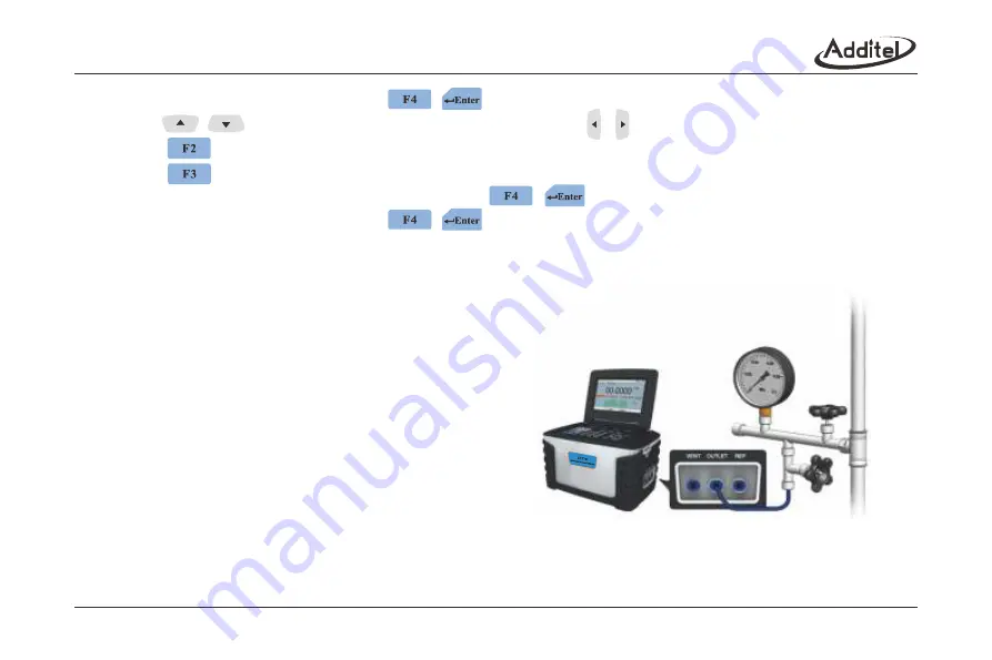
 Connect the calibrator to the dial pressure gauge 

              as shown in Figure 3-20.


 Connect the REF/FLT port to the low pressure port 

                of the differential pressure gauge.

       2. New Task 

Figure 3-20 Calibrating a dial pressure gauge

37

/FLT

Содержание ADT761 Series

Страница 1: ...ADT761 Series Automated Pressure Calibrator...

Страница 2: ...Additel Corporation ADT761 Series Automated Pressure Calibrator Version 1903V06 User Manual Please download the latest version from www additel com...

Страница 3: ...instructions for the ADT761 Series Automated Pressure Calibrator To ensure correct operation and safety please follow the instructions in this manual Additel reserves the right to change the contents...

Страница 4: ...6 2 1 3 RS 232 interface 6 2 1 4 Keypad 7 2 1 5 Pneumatic port 8 2 2 Inital preparation 8 2 2 1 Battery installation 8 2 2 2 Changing the belt strap 9 2 2 3 Pneumatic connection 9 2 2 4 View the displ...

Страница 5: ...1 13 Vent 19 3 2 HART 20 3 2 1 Poll 20 3 2 2 Process variables 21 3 2 3 Setup 22 3 2 4 Service 23 3 3 Typical applications in the main screen 24 3 3 1 Calibrating pressure gauges 24 3 3 2 Calibrating...

Страница 6: ...measure 35 3 4 9 2 Current source 35 3 4 9 3 High low range 35 3 4 9 4 External pressure module 36 3 4 9 5 Self tune 36 3 4 10 RS232 setup 36 3 5 Task 36 3 5 1 Calibrating dial pressure gauges 37 3 5...

Страница 7: ...761 Basic differences 50 5 2 Gas head correction 50 5 3 1 Digital barometer 50 5 3 2 Mercurial barometer 52 5 3 3 Aneroid barometer 53 5 3 4 Barometer altimeter 54 5 3 5 Pressure transmitter 55 5 3 6...

Страница 8: ...t apply pressures greater than the maximum working pressure Additel s warranty will not cover this application Not for use in flammable high humidity or dusty environments Only charge with supplied ba...

Страница 9: ...esolve control issues The vent port should not face the operator during venting Do not apply excessive voltage or current to the electrical terminals Do not use any adapter other than Additel model 98...

Страница 10: ...ovides many different ways to calibrate and test a variety of devices such as dial pressure gauges digital pressure gauges pressure transmitters pressure switches and I P converters 1 2 Features Autom...

Страница 11: ...to 615 psi a 100 to 1200 hPa 2 5 to 2 5 mbar 1 to 1 inH O 2 25 to 25 mbar 10 to 10 inH O 2 0 95 to 2 5 bar 13 5 to 35 psi 0 90 to 2 5 bar 13 to 35 psi 0 90 to 2 5 bar 13 to 35 psi 0 95 to 2 5 bar 13 5...

Страница 12: ...ask and Setup keys Portable Automated Pressure Calibrator Lock Strap Connections Vent Port Outlet Port REF FLT Port Battery Shortcut Keys On Off Control Keys Numeric Keypad Status Bar Measure Source M...

Страница 13: ...232 interface DC27V input Introduction Current measure Voltage measure Switch test HART communication Current output external power Current output internal power Loop power supply at 24V Works with AD...

Страница 14: ...7 2 1 4 Keypad Table 2 3 Key functions...

Страница 15: ...contains a filter for internal pump The filter should be changed when dirty as shown in figure 2 3 VENT port The port which pressure is released from the system 2 2 Initial preparation 2 2 1 Battery i...

Страница 16: ...ADT761 D Figure 2 7 shows pneumatic connection of ADT761 L ADT761 LA ADT761 M ADT761 MA ADT761 H and ADT761 HA connect the OUTLET and REF FLT ports to the UUT or use plugs when necessary 2 2 4 View th...

Страница 17: ...n in Figure 2 8 Connect the power supply for charging if power is low 2 3 2 Setting the system date and time Refer to section 3 4 4 to set date and time 2 3 3 Generating a pressure Ensure the source s...

Страница 18: ...select between the MEASURE and SOURCE window press till the desired window is highlighted in orange The softkeys displayed at the bottom of the screen relate to the selected mode Press or to select w...

Страница 19: ...or in standby mode The calibrator will automatically vent when switching ranges 2 Connection Complete the pneumatic connection as shown in Figure 3 3 or Figure 3 4 3 Entering a value Use the numeric...

Страница 20: ...stable condition as defined in the CONTROL SETUP Section 3 4 1 the color of the displayed value will change from black to green 3 1 3 Pressure measure 1 Select the High Low Pressure Range in measure m...

Страница 21: ...by mode to change from sourcing pressure to current 2 Connection Complete the electrical connection as shown in Figure 3 6 or Figure 3 7 3 Power supply Press to select internal loop power or external...

Страница 22: ...black to red and the calibrator will issue the alarm If the value exceeds the measure limit of the calibrator the value will be shown as _ _ _ _ _ _ _ _ and the calibrator will issue the alarm 2 Conn...

Страница 23: ...rnal pressure module is online The home screen will show three windows with the TRIPLE DISPLAY when it is enabled in DISPLAY SETUP Both the MEASURE and SOURCE can be changed to read the external press...

Страница 24: ...gh Low Range pressure Current Voltage measure or external pressure module Zero can be done within 1 FS of the pressure or 0 1 FS of the Current Voltage 3 1 11 Step 1 Setup Press to setup the step para...

Страница 25: ...ll prompt the user to reset the limits Stroke mode select the One Way or the Two Way Wait Time 1 For the auto mode only the range is 1 3600 seconds 2 When SOURCE is set to Current the wait time is tim...

Страница 26: ...list press and hold for two seconds or press and select the snapshot item Press to page up and down Press to delete the record s The record s can be uploaded to a computer by the RS232 port to Additel...

Страница 27: ...Vent P pressure in the Control Setup 3 2 HART 3 2 1 Poll 1 Connect Use the internal series resistor and internal 24V loop power supply as shown in Figure 3 13 Use the internal series resistor and ext...

Страница 28: ...window of the Home screen and the HART icon will display in the status bar after connection to the transmitter is established Press to disconnect the HART instrument and the HART icon will disappear...

Страница 29: ...y Read only Read only Read only Read and write Read and write Read and write Read and write Read and write Read only Description Transmitter manufacturer Manufacturer model number Manufacturer device...

Страница 30: ...ng to the HART Protocol 2 D A output trim Through adjusting the coefficient of current output the transmitter s PVAO is consistent with loop mA Press to trim the Zero DAC Zero and Span DAC Gain or pre...

Страница 31: ...press to put the pressure value sourced by calibrator into the Trim Value input box 3 3 Typical applications in the main screen 3 3 1 Calibrating pressure gauges 1 Prepare Select High range or Low ran...

Страница 32: ...nually or by the step function Section 3 1 11 4 Record the measure value manually or by using snapshot Section 3 1 12 after the pressure has stabilized 3 3 3 Calibrating HART transmitters 1 Prepare Se...

Страница 33: ...include 4 process variables 3 3 4 Calibrating pressure switches 1 Prepare Select the High or Low range in SOURCE mode Select the Switch in MEASURE mode 2 Connect Complete the pneumatic and electrical...

Страница 34: ...e 3 19 DO NOT over pressure the calibrator DO NOT use the calibrator as the pressure source Check the load ability of the UUT for using the internal 24V power supply 3 Source the current manually or b...

Страница 35: ...pe will be shown on the status bar in the home screen 2 Ctrl LRV and Ctrl URV Control limits A range smaller than the calibrator range may be selected to limit the output pressure to avoid over pressu...

Страница 36: ...trip point 6 Auto Zero If enabled the calibrator will automatically zero pressure value when it is in vent state and record the offset If Absolute pressure type selected the Auto Zero will be disable...

Страница 37: ...light after a set time Accepted timeout period Never 5 minutes 10 minutes 30 minutes 1 hour 2 hours and 4 hours The backlight will come on by pressing any key The backlight is disabled in the Step fun...

Страница 38: ...high low range for pressurizing to the leak test point automatically with the calibrator P Module pressurize with an external pressure source and measure the real pressure with an external pressure mo...

Страница 39: ...as the start pressure 4 The test time will count down Real leakage Start pressure Real pressure 5 When the test time reaches zero the calibrator records the displayed pressure as the end pressure and...

Страница 40: ...during venting as shown in Figure 3 20 The vent port should not face the operator 2 Run Select vent under the tools icon in the setup screen The 761 will automatically switch to the high range Press t...

Страница 41: ...layed 3 4 9 System Calibration The calibrator should be powered to warm up 30 minutes prior to starting the calibration To ensure optimum instrument operation the current voltage measure the current s...

Страница 42: ...dardized unit generates signal to the calibrator When the measured value is stable Press to record and continue press to review 3 4 9 2 Current source 1 Calibration points The default is 4mA 20mA that...

Страница 43: ...232 setup in the setup screen Set the baudrate databits and stopbits Press numeric keypad to set the address and the range is 001 121 3 5 Task The calibrator provides the task function for automated c...

Страница 44: ...e repeated but only the last result will be recorded Carefully select your operation as they cannot be reversed View the run information and report The failures are red and stands for no record The da...

Страница 45: ...librator will use dual range if needed 5 Over pressuring can result in damage to the UUT Pressure type gauge absolute or differential Accuracy 1 Preselected accuracies are available 2 Custom X XX When...

Страница 46: ...ure to stabilize Input the reading of the UUT that cannot exceed 110 full scale of the UUT When continuing with no input the standard value will be recorded as the indicator If tapping is enabled the...

Страница 47: ...pt Accuracy settings where the accuracy can be defined as a of FS or a of reading or a combination of FS and of reading 3 5 3 Calibrating pressure transmitters When calibrating a pressure transmitter...

Страница 48: ...be equal 3 The calibrator will automatically select the range for higher precision 4 The calibrator will use the dual range if needed 5 Over pressuring the UUT may result in damage to the UUT Pressure...

Страница 49: ...Source Internal Pressure or Pressure Module Select the run mode 1 Automatic When the pressure is stable the calibrator will count down based on the Reading Time in seconds before taking the measureme...

Страница 50: ...ng a common pressure transmitter Section 3 5 3 3 Run Poll HART devices automatically if needed or press to do it manually Section 3 2 1 Compare the range of the task settings with the real range of th...

Страница 51: ...Dead band range is the minimum and maximum of the dead band Dead band is the pressure difference between the change of states i e OPEN CLOSE or CLOSE OPEN Set point The pressure which the switch will...

Страница 52: ...hanged between Standby and Control The calibrator will automatically switch to the suitable range if needed The calibrator can change the slew rate of the pressure control automatically according to t...

Страница 53: ...n be edited individually Range of UUT 1 Cannot exceed the measure the range of the calibrator 2 The high and low limit cannot be equal Cycles 1 3 3 Run Input the information before running including t...

Страница 54: ...nformation Select the device information in the setup screen View the software revision factory date serial number and so on View the information of the high low range inside View the current atmosphe...

Страница 55: ...run the vent function for self protection The system is failing to connect with internal pressure module but it is trying over and over again The internal valve s temperature is abnormal or irregular...

Страница 56: ...DT761 D ADT761 L ADT761 M ADT761 H ADT761 LA ADT761 MA ADT761 HA ADT761 BP 2 5 to 2 5 mbar 1 to 1 inH2 O 25 to 25 mbar 10 to 10 inH2 O 0 95 to 2 5 bar 13 5 to 35 psi 0 95 to 2 5 bar 13 5 to 35 psi 0 9...

Страница 57: ...bled the calibrator will display the correct result automatically according to the setting of parameters Set the Height value in accordance with the Metric or English Units Set the Density value in ac...

Страница 58: ...ts 1 The range is 2 17 2 Scale the steps in accordance with the linear the UUT for the default 3 Every point can be edited Tolerance 1 Given 0 1 0 2 0 3 0 4 0 5 1 2 5 mbar 2 Custom the custom range is...

Страница 59: ...wn in Figure 5 2 Connect the REF FLT port to the low pressure port of the differential pressure gauge 2 New Task name 1 Enter an alphanumeric name and press to input special codes 2 The name cannot be...

Страница 60: ...relative humidity the default is 40 RH and the range is 0 100 RH Stroke mode One Way or Two Way Wait for the displayed pressure to stabilize Input the value from the UUT After inputting the value for...

Страница 61: ...ng task 3 The characters of the input task name cannot exceed 12 spaces Range of UUT 1 Range 0 1bar 1 2bar 2 Cannot exceed the output range of the calibrator 3 The high and low limit cannot be equal 4...

Страница 62: ...umidity the default is 40 RH and the range is 0 100 RH Stroke mode One Way or Round Trip Wait for the displayed pressure to stabilize Input the value from the UUT After inputting the value for the UUT...

Страница 63: ...ons Internal pressure ranges and accuracy Table A 1 Pressure ranges Model Pressure Range Range 25 to 25 mbar 10 to 10 inH 2O 0 95 to 1 bar 13 5 to 15 psi 0 95 to 7 bar 13 5 to 100 psi 2 5 to 2 5 mbar...

Страница 64: ...a r a 1 2 to 50 psi a 0 9 to 2 5 bar 13 to 35 psi 0 1 to 3 5 ba r a 1 7 to 50 psi a 0 9 to 2 5 bar 13 to 35 psi 0 1 to 3 5 ba r a 1 7 to 50 psi a 100 to 1 200 hPa 0 02 FS 0 02 FS 0 02 FS 0 03 FS 0 02...

Страница 65: ...f 15 25 Note 2 input features 1 Voltage measurement input impedance 1M Max input voltage is 300V DC 2 Current measurement input impedance 10 Max input current is 1A DC Electrical source ambient temper...

Страница 66: ...stance voltage 4 V 2 Short circuit protected Display 7 0 800 480 pixels color LCD Dimensions and weight 296 w 186 h 180 d mm and approx 5 6kg Electrical interface 4mm electrical jack Charging interfac...

Страница 67: ...Additel Corporation 2900 Saturn St B Brea CA 92821 USA Phone 714 998 6899 Email service additel com website www additel com...

Отзывы: