28
Chapter 1
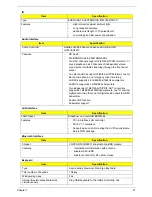
MDC Card
Camera
Finger Print Board
Battery
Item
Specification
Chipset
Intel® Wireless WiFi Link 5100/5300
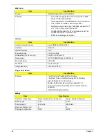
Features
•
The modem supports ITU-T V.92, V.90, V.34 (33600
bits/s), V.32bis and fallbacks.
•
It also supports V.42 LAPM, MNP 2-4 error correction.
•
V.44, V.42bis and MNP 5 data compression.
•
Send and receive rates up to 14400bps, support ITU-T
V.17, V.29, V.27ter, and V.21Ch2 fax.
•
TIA/EIA 602 Standard for AT command set, and Fax
TIA/EIA 578 Class 1 command set.
•
DTMF and call progress monitor
Item
Specification
Vendor and model name
Suyin CN0314-SN30-OV03-1
Interface
USB 2.0
Optical aperture
F2.0
Focusing range
40 cm to infinity
Dimensions (L x W x H mm)
65 x 9.0 x 5.30 (±0.20)
Sensor type
OV7725 CMOS Sensor 350K Pixel
Pixel resolution
640 x 480
Pixel size
6.0µm x 6.0µm
Image size (mm)
3.98 (H) x 2.95 (V)
Item
Specification
Features
TruePrint® and TrueMatch® Technology.
TrueNav® Cursor and Menu Navigation Technology
High Definition 128 x 8 Pixel Array
Multiple battery-friendly operating modes @ 3.3V
Built-in low power Finger Detection w/ remote wakeup
capability
USB 2.0 Full Speed Interface
Item
Specification
Vendor & model name
Sanyo, Simplo, Sony, Panasonic
Sanyo, Simplo, Panasonic
Battery Type
Li-ion
Li-ion
Pack capacity
4400 mAh
4800 mAh
Number of battery cell
6
8
Package configuration
3S2P
4S2P
Содержание Aspire 7230
Страница 6: ...VI ...
Страница 10: ...X Table of Contents ...
Страница 54: ...44 Chapter 2 3 Reboot the system and key in the selected string qjjg9vy 07yqmjd etc for the BIOS user password ...
Страница 85: ...Chapter 3 75 5 Remove the bracket from the board 6 Remove the Finger Print Reader board from the Upper Cover ...
Страница 92: ...82 Chapter 3 4 Grasp the Subwoofer Module and lift it up to remove ...
Страница 94: ...84 Chapter 3 4 Lift the ExpressCard module away from the upper cover ...
Страница 101: ...Chapter 3 91 4 Lift up the bezel and remove it from the LCD Module ...
Страница 105: ...Chapter 3 95 5 Grasp the panel by both ends and lift to remove ...
Страница 107: ...Chapter 3 97 4 Remove the LCD brackets by pulling away from the LCD Panel as shown ...
Страница 110: ...100 Chapter 3 8 Connect the left and right Inverter cables 9 Connect the camera cable ...
Страница 113: ...Chapter 3 103 3 Tighten the four 4 captive screws on the heatsink 4 Connect the Fan cable to the Mainboard ...
Страница 118: ...108 Chapter 3 4 Connect the two FFC cables as shown 5 Connect the cable as shown ...
Страница 206: ...196 Appendix C ...


