154
Chapter 4
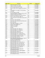
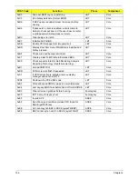
0x6A
Display external cache size on the screen if it is non-
zero.
LBT
Core
0x6C
Display shadow message
LBT
Core
0xCA
post EISA init
LBT
Core
0x70
Check flags in CMOS and in the TrustedCore data
area for errors detected during POST. Display error
messages on the screen.
LBT
Core
0x72
Check status bits to see if configuration problems
were detected. If so, display error messages on the
screen.
LBT
Core
0x4F
Initialize MultiBoot. Allocate memory for old and new
MultiBoot history tables.
LBT
Core
0xCD
Reclaim console vector after HW vectors initialized.
LBT
Core
0x7D
Initialize Intelligent System Monitoring.
LBT
Core
0x7E
The Coprocessor initialization test. Use the floating
point instructions to determine if a coprocessor
exists instead of the ET bit in CR0.
LBT
Core
0xC1
Check Boot Type (Server BIOS)
LBT
Core
0x80
Disable onboard COM and LPT ports before testing
for presence of external I/O devices.
LBT
Core
0xCA
Redirect Int 15h to enable target board to use remote
keyboard (PICO BIOS).
LBT
Core
0x88
Initialize interrupt controller.
LBT
Core
0x81
Run late device initialization routines.
LBT
Core
0x87
Initialize motherboard configurable devices.
LBT
Core
0x85
Display any ESCD read errors and configure all PnP
ISA devices.
LBT
Core
0x82
Test and identify RS232 ports.
LBT
Core
0x84
Test and identify parallel ports.
LBT
Core
0x86
Initialize onboard I/O and BDA according to CMOS
and presence of external devices.
LBT
Core
0x83
Configure Fisk Disk Controller.
LBT
Core
0xCE
Initialize digitizer device and display installed
message if successful.
LBT
Core
0x89
Enable non-maskable interrupts.
LBT
Core
0x8C
Initialize both of the floppy disks and display an error
message if failure was detected. Check both drives
to establish the appropriate diskette types in the
TrustedCore data area
LBT
Core
0xCB
Redirect Int 13h to Memory Technologies Devices
such as ROM, RAM, PCMCIA, and serial disk (PICO
BIOS).
LBT
Core
0xCD
Remap I/O and memory address space for PCMCIA
(PICO BIOS).
LBT
Core
0x90
Initialize hard-disk controller. If the CMOS ram is
valid and intact, and fixed disks are defined, call the
fixed disk init routine to initialize the fixed disk
system and take over the appropriate interrupt
vectors.
LBT
Core
POST Code
Function
Phase
Component
Содержание Aspire 7230
Страница 6: ...VI ...
Страница 10: ...X Table of Contents ...
Страница 54: ...44 Chapter 2 3 Reboot the system and key in the selected string qjjg9vy 07yqmjd etc for the BIOS user password ...
Страница 85: ...Chapter 3 75 5 Remove the bracket from the board 6 Remove the Finger Print Reader board from the Upper Cover ...
Страница 92: ...82 Chapter 3 4 Grasp the Subwoofer Module and lift it up to remove ...
Страница 94: ...84 Chapter 3 4 Lift the ExpressCard module away from the upper cover ...
Страница 101: ...Chapter 3 91 4 Lift up the bezel and remove it from the LCD Module ...
Страница 105: ...Chapter 3 95 5 Grasp the panel by both ends and lift to remove ...
Страница 107: ...Chapter 3 97 4 Remove the LCD brackets by pulling away from the LCD Panel as shown ...
Страница 110: ...100 Chapter 3 8 Connect the left and right Inverter cables 9 Connect the camera cable ...
Страница 113: ...Chapter 3 103 3 Tighten the four 4 captive screws on the heatsink 4 Connect the Fan cable to the Mainboard ...
Страница 118: ...108 Chapter 3 4 Connect the two FFC cables as shown 5 Connect the cable as shown ...
Страница 206: ...196 Appendix C ...

