background image

38

Chapter 2

Power

The Power screen allows the user to configure various CPU and power management options and device 
wakeup behavior.

The table below describes the items, menus, and submenus in this screen. Settings in 

boldface

 are the default 

and suggested parameter settings. 

Parameter

Description

Option

C1E Configuration

Enable or Disable C1E Dual-Core related 
CPU power State.

Auto

, Griffin Mode or 

Disabled

CPU Throttle

Enable or disable CPU Throttle.

Disabled

 or Enabled

CPU Spread Spectrum

Enable or disable CPU Spread Spectrum.

Disabled

 or Enabled

iGPU Spread Spectrum

Set the iGPU Spread Spectrum percentage.

1.00%, 2.00%, 

3.00%

4.00%, 5.00% or 
Disabled

PCIE Spread Spectrum

Enable or disable PCIE Spread Spectrum.

Disabled

 or Enabled

SATA Spread 
Spectrum

Enable or disable SATA Spread Spectrum.

Linear Down

 or Disabled

PState Configuration

Enable or disable ACPI PState Support

Enabled

 or Disabled

USB CSC Resume

Enable or disable wake up from S3 by USB 
plug or unplug.

Disabled

 or Enabled

Cannot_Find_String

Enable or disable the Cannot_Find_String 
message during boot.

Disabled

 or Enabled

HIPM

Enable or disable Aggressive Link Power 
Management (HIPM).

Disabled

 or Enabled

SATA FPCI Clock

Set the SATA low power control level.

133 MHz 

or 200 MHz

SATA Low Power

Set SATA low power control type.

SALP Off

, Partial on, 

Slumber on or SALP On

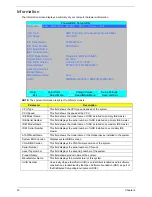
             PhoenixBIOS Setup Utility

Information     Main     Advanced

Security

Boot

Power

Exit

Item Specific Help

C1E Configuration

[Auto]

Enable or Disable

CPU Throttle:

[Disabled]

C1E Dual-Core related

CPU Spread Spectrum:

[Enabled]

CPU power State.

iGPU Spread Spectrum:

[3.00% Triangular Centre]

PCIE Spread Spectrum:

[Disabled]

Auto enables C1E 

SATA Spread Spectrum:

[Linear Down]

if dual core is

PState Configuration

[Enabled]

detected and disables

USB CSC Resume

[Disabled]

C1E if single core

DIPM

[Disabled]

is detected.

HIPM

[Disabled]

SATA FPCI Clock:

[133Mhz]

SATA Low Power

[SALP OFF]

PCI Clocks:

[Enabled]

AltVid

[Disabled]

ASPM (L0s/L1s)

[Disabled]

PCIE Lane Swizzle:

[Disabled]

F1

 Help           

↑↓

 Select Item           

F5/F6

 Change Values       

F9

 Setup Defaults

ESC

 Exit         

←→

 Select Menu      

Enter

 Select

X

Sub-Menu 

   F10

 Save and Exit

Содержание Aspire 7230

Страница 1: ...Aspire 7230 7530 7530G Series Service Guide PRINTED IN TAIWAN Service guide files and updates are available on the ACER CSD web for more information please refer to http csd acer com tw ...

Страница 2: ...II Revision History Please refer to the table below for the updates made on Aspire 7230 7530 7530G Series service guide Date Chapter Updates ...

Страница 3: ...pect to the contents hereof and specifically disclaims any warranties of merchantability or fitness for any particular purpose Any Acer Incorporated software described in this manual is sold or licensed as is Should the programs prove defective following their purchase the buyer and not Acer Incorporated its distributor or its dealer assumes the entire cost of all necessary servicing repair and an...

Страница 4: ... bits and pieces of additional information related to the current topic WARNING Alerts you to any damage that might result from doing or not doing specific actions CAUTION Gives precautionary measures to avoid possible hardware or software problems IMPORTANT Reminds you to do specific actions relevant to the accomplishment of procedures ...

Страница 5: ... NOT be covered in this generic service guide In such cases please contact your regional offices or the responsible personnel channel to provide you with further technical details 2 Please note WHEN ORDERING FRU PARTS that you should check the most up to date information available on your regional web or channel If for whatever reason a part number change is made it will not be noted in the printe...

Страница 6: ...VI ...

Страница 7: ...e BIOS Utility 29 Information 30 Main 31 Advanced 32 Security 34 Boot 37 Power 38 Exit 40 BIOS Flash Utility 41 Remove HDD BIOS Utility 42 Machine Disassembly and Replacement 45 Disassembly Requirements 45 General Information 46 Pre disassembly Instructions 46 Disassembly Process 46 External Module Disassembly Process 47 External Modules Disassembly Flowchart 47 Removing the Battery Pack 48 Removi...

Страница 8: ...Cable 96 LCD Module Reassembly Procedure 98 Replacing the LCD Panel 98 Replacing the LCD Bezel 101 Main Module Reassembly Procedure 102 Replacing the CPU 102 Replacing the CPU Fan Module 102 Replacing the Mainboard 104 Replacing the Bluetooth Board 104 Replacing the ExpressCard Module 105 Replacing the Subwoofer Module 106 Replacing the Finger Print Reader 107 Replacing the eKey Board 109 Replacin...

Страница 9: ... Reader Failure 143 Thermal Unit Failure 144 HDTV Switch Failure 144 External Mouse Failure 145 Other Failures 145 Intermittent Problems 146 Undetermined Problems 146 POST Codes Tables 147 Chipset POST Codes 147 Core POST Codes 149 Jumper and Connector Locations 157 Top View 157 Bottom View 158 Clearing Password Check and BIOS Recovery 159 Clearing Password Check 159 BIOS Recovery by Crisis Disk 1...

Страница 10: ...X Table of Contents ...

Страница 11: ...mpron processor NVIDIA nForce MCP77MH Acer InviLink 802 11b g System Memory Dual Channel DDR2 SDRAM support Up to 2 GB of DDR2 667 MHz memory upgradeable to 4 GB using two soDIMM modules TV Tuner Digital TV tuner supporting DVB T Display and graphics 17 WXGA 1440 x 900 NVIDIA GeForce 9100M G NVIDIA GeForce 9400M NVIDIA GeForce 9600M GT Storage subsystem 2 5 hard disk drive Optical drive options Bl...

Страница 12: ...ery pack Privacy control Acer Bio Protection fingerprint solution BIOS user supervisor HDD passwords Kensington lock slot Communication Acer Video Conference featuring Integrated Acer Crystal Eye webcam Optional Acer Xpress VoIP phone WLAN Acer InviLink 802 11b g WPAN Bluetooth 2 0 Enhanced Data Rate EDR LAN Gigabit Ethernet Wake on LAN ready Modem 56K ITU V 92 Power subsystem ACPI 3 0 71 W 4800 m...

Страница 13: ...ack Line in jack Ethernet RJ 45 port Modem RJ 11 port DC in jack for AC adapter Environment Temperature Operating 5 C to 35 C Non operating 20 C to 65 C Humidity non condensing Operating 20 to 80 Non operating 20 to 80 NOTE Items marked with denote only selected models The specifications listed above are for reference only The exact configuration of your PC depends on the model purchased ...

Страница 14: ... 1V S1G2 Processor AMD Griffin DDR II SMDDR_VTERM 1 8VSUS TPS51116REGR MCP77M Sabie Lion SPI ROM Touch Pad CPU Fan Speaker Audio Amplifier SPIDF Phone Jack Line in x1 x1 MIC Jack Int MIC Azalia AudioController RealTek ALC888 LVDS CRT MXM Connector PCI Express 16X INT or EV selector Resistor CPU CORE ISL6265A LVDS CRT SYSTEM POWER ISL6237 HDMI x2 DDRII 667 800 MHz 14 318MHz SATA HDD SATA1 HDMI CONN...

Страница 15: ...hone Internal microphone for sound recording 3 Display screen Also called Liquid Crystal Display LCD displays computer output 4 Power button Turns the computer on and off 5 Easy launch buttons Buttons for launching frequently used program 6 Palmrest Comfortable support area for your hands when you use the computer 7 Status indicators Light Emitting Diodes LEDs that light up to show the status of t...

Страница 16: ...ch functions like a computer mouse 10 Keyboard For entering data into your computer 11 Speakers Left and right speakers deliver stereo audio output 12 Empowering key Launch Acer Empowering Technology No Icon Item Description 1 CIR receiver Receives signals from a remote control 2 Unlimited volume control wheel Adjust the volume of the audio out 3 5 in 1 card reader Accepts Secure Digital SD MultiM...

Страница 17: ...s to a display device e g external monitor LCD projector 5 HDMI HDMI Connects to a television or display device with HDMI input only for certain models 6 USB 2 0 port Connect to USB 2 0 devices e g USB mouse USB camera 7 Headphones speaker line out jack with S PDIF support Connects to audio line out devices e g speakers headphones Microphone jack Accepts input from external microphones Line in jac...

Страница 18: ...cts the optical disk from the drive 6 Emergency eject hole Ejects the optical drive tray when the computer is turned off Note Insert a paper clip into the emergency eject hole to eject the optical drive tray when the computer is off 7 RF in port Accepts input signals from digital TVtuner devices only for certain models 8 Modem RJ 11 port Connects to a phone line 9 Kensington lock slot Connects to ...

Страница 19: ...l 4 Battery lock Locks the battery in position 5 Hard disk bay Main Houses the computer s hard disk secured with screws 6 Hard disk bay Secondary Houses the computer s hard disk secured with screws Only for certain models 7 Memory compartment Houses the computer s main memory 8 Ventilation slots and cooling fan Enable the computer to stay cool even after prolonged use Note Do not cover or obstruct...

Страница 20: ...il and programmable buttons run the Acer Launch Manager Icon Function Description Power Indicates the computer s power status Battery Indicates the computer s battery status HDD Indicates when the hard disk drive is active Num Lock Lights up when Num Lock is activated Caps Lock Lights up when Caps Lock is activated Icon Function Description Empowering Technology Launch Acer Empowering Technology u...

Страница 21: ...certain models to scroll up or down and move left or right a page This fingerprint reader or button mimics your cursor pressing on the right scroll bar of Windows applications NOTE When using the Touch Pad keep it and your fingers dry and clean The Touch Pad is sensitive to finger movement hence the lighter the touch the better the response Tapping too hard will not increase the Touch Pad s respon...

Страница 22: ...percase Num Lock Fn F11 When Num Lock is on the embedded keypad is in numeric mode The keys function as a calculator complete with the arithmetic operators and Use this mode when you need to do a lot of numeric data entry A better solution would be to connect an external keypad Scroll Lock Fn F12 When Scroll Lock is on the screen moves one line up or down when you press the up or down arrow keys r...

Страница 23: ...rk domain M Minimizes all windows R Open the Run dialog box T Cycle through programs on the taskbar U Open Ease of Access Center X Open Windows Mobility Center BREAK Display the System Properties dialog box SHIFT M Restore minimized windows to the desktop TAB Cycle through programs on the taskbar by using Windows Flip 3 D SPACEBAR Bring all gadgets to the front and select Windows Sidebar CTRL F Se...

Страница 24: ...Acer Empowering Technology Fn F4 Sleep Puts the computer in Sleep mode Fn F5 Display toggle Switches display output between the display screen external monitor if connected and both Fn F6 Screen blank Turns the display screen backlight off to save power Press any key to return Fn F7 Touch Pad toggle Turns the internal Touch Pad on and off Fn F8 Speaker toggle Turns the speakers on and off Fn Brigh...

Страница 25: ...lt Gr and then press the 5 key at the upper center of the keyboard NOTE Note Some fonts and software do not support the Euro symbol Please refer to www microsoft com typography faq faq12 htm for more information The US dollar sign 1 Open a text editor or word processor 2 Hold Shift and then press the 4 key at the upper center of the keyboard NOTE This function varies by the operating system versio...

Страница 26: ...gerNav With Acer Bio Protection Fingerprint Solution you can now enjoy an extra layer of protection for your personal computer as well as the convenience of accessing your daily tasks with a simple swipe of your finger For more information refer to the Acer Bio Protection help files Acer GridVista dual display compatible NOTE This feature is only available on certain models To enable the dual moni...

Страница 27: ...tible allowing two displays to be partitioned independently AcerGridVista is simple to set up 1 Run Acer GridVista and select your preferred screen configuration for each display from the task bar 2 Drag and drop each window into the appropriate grid 3 Enjoy the convenience of a well organized desktop NOTE Please ensure that the resolution setting of the second monitor is set to the manufacturer s...

Страница 28: ... s 1 8GHz 2 3GHz CPU CPU package 638 Pin Lidless Micro PGA package 35mm 35mm Features The AMD Socket S1g2 processor is a superb high performance product for mobile systems With HyperTransport 3 technology bus and on chip memory controller CPU core voltage VCC_CORE0 based on CPU VCC_CORE1 based on CPU CPU_VDDNB based on CPU VLDT 1 2V_HT VDD I O 1 8VSUS CPU Memory Interface SMDDR_VTEM Level Fan On T...

Страница 29: ...isual user interface support Integrated GeForce DirectX 10 model 4 0 graphics processor1 Unified Shader model 4 0 for geometry vertex and pixel processor2 NVIDIA Intellisample AA technology Next generation NVIDIA PureVideo HD video processor for full HD content decode and Playback with long battery life or with lower cost single core CPUs PowerMizer SX System eXtensions reduces system power usage ...

Страница 30: ...annel audio Supports 32 bit 192 kHz audio functionality LPC bus 1 0 compatible interface Integrated programmable clock synthesizer with spread spectrum support Support for Microsoft Vista ReadyDrive feature using commodity hard drives and flash devices Support for direct input from accelerometer for more responsive hard disk park control ASF 2 0 support for remote manageability Separately programm...

Страница 31: ... SDRAM memory interface design Supports DIMM Speed 533 677 Mhz Memory module combinations You can install memory modules in any combinations as long as they match the above specifications Slot 1 Slot 2 Total Memory 0MB 512MB 512MB 0MB 1024MB 1024MB 0MB 2048MB 2048MB 512MB 512MB 1024MB 512MB 1024MB 1536MB 512MB 2048MB 2560MB 1024MB 0MB 1024MB 1024MB 512MB 1536MB 1024MB 1024MB 2048MB 1024MB 2048MB 3...

Страница 32: ...le Maximum Frequency 100 mV double amplitude 0 30 MHz Item Specification Vendor model name Sony BC 5500S Performance Specification With CD Diskette With DVD Diskette Transfer rate MB sec Sustained Max 2 4 Mbytes sec Sustained Max 11 Mbytes sec Buffer Memory 4 5 MB Interface SATA Applicable disc format Applicable media types BD ROM Single and Dual Layer BD R Single and Dual Layer BD RE Single and D...

Страница 33: ...le dual layer PTP OTP DVD R single dual layer DVD R single double layer DVD RW DVD RW CD DA CD ROM CD ROM XA Photo CD Multi session Video CD CD I FMV CD Extra CD Plus CD R and CD RW Loading mechanism Drawer Solenoid Open Tact SW Open Emergency Release draw open hole Power Requirement Input Voltage DC 5 V 5 Item Specification Thermal Sensor Chip GMT 786 W83L771 Package 8 pin SSOP Features Thermal s...

Страница 34: ...onsumption watt 4 68 Weight g Typical 715 Maximum 735 Physical Size mm 382 H x 244 5 V x 6 7 D Electrical Interface LVDS Support Color 262 144 Viewing Angle degree Horizontal Right Left Vertical Upper Lower 40 45 40 45 15 20 20 25 Temperature Range C Operating Storage shipping 0 50 20 60 Item Specification Chipset WND WPCE775CA0DG Features Share BIOS memory Support for SPI flash memories Flash pag...

Страница 35: ...z pixel data rate Support version 1 1 of the Display Port interface standard for flat panel display Projectors PCs and CE devices High quality video scaling and filtering Up to WUXGA resolution support on HDMI and up to 2560 X 1600 resolution supporting Display Port mode SPWG compliant Support for LCD panel EDID Power based on MCP67M NB_CORE for MCP77M CORE Power 1 0V 1 1V_NB for MCP77 Hyper Trans...

Страница 36: ...terfaces Secure Digital SD MultiMediaCard MMC Mini SD Micro SD T flash RS MMC Mobile MMC and MMC micro Memory Stick MS Memory Stick PRO MS PRO MS Duo MS PRO Duo and Micro MS M2 MSPRO HG Duo 8 bit mode xD Picture Card xD including Type M and Type H Support hardware ECC Error Correction Code function Support hardware CRC Cyclic Redundancy Check function Programmable clock rate for flash memory card ...

Страница 37: ...ing All DACs supports 44 1k 48k 96k 192kHz sample rate All ADCs support 44 1k 48k 96k sample rate Two independent 16 20 24 bit S PDIF OUT converters support 44 1k 48k 96k 192kHzsample rate one for nominal digital audio the other one for digital audio output to HDMI transmitter Enable VoIP function Subwoofer support Item Specification LAN Chipset BroadCom Lan controller BCM5764 Features PCI E inter...

Страница 38: ...4 SN30 OV03 1 Interface USB 2 0 Optical aperture F2 0 Focusing range 40 cm to infinity Dimensions L x W x H mm 65 x 9 0 x 5 30 0 20 Sensor type OV7725 CMOS Sensor 350K Pixel Pixel resolution 640 x 480 Pixel size 6 0µm x 6 0µm Image size mm 3 98 H x 2 95 V Item Specification Features TruePrint and TrueMatch Technology TrueNav Cursor and Menu Navigation Technology High Definition 128 x 8 Pixel Array...

Страница 39: ...ange boot device without entering BIOS SETUP Utility Navigating the BIOS Utility There are six menu options Information Main Advanced Security Boot and Exit Follow these instructions To choose a menu use the left and right arrow keys To choose an item use the up and down arrow keys To change the value of a parameter press F5 or F6 A plus sign indicates the item has sub items Press Enter to expand ...

Страница 40: ...f the system Serial Number This field displays the serial number of this unit Asset Tag Number This field displays the asset tag number of the system Product Name This field shows product name of the system Manufacturer Name This field displays the manufacturer of this system UUID Number Universally Unique Identifier UUID is an identifier standard used in software construction standardized by the ...

Страница 41: ...t Enables disables the system boot from LAN remote server Option Enabled or Disabled F12 Boot Menu Enables disables Boot Menu during POST Option Disabled or Enabled D2D Recovery Enables disables D2D Recovery function The function allows the user to create a hidden partition on hard disc drive to store operation system and restore the system to factory defaults Option Enabled or Disabled SATA Mode ...

Страница 42: ...Reset Configuration Data Clear the Extended System Configuration Data ESCD area using this option N A LPC Port 80 Enable or Disable LPC Port 80 N A PCI Hot Plug Resources Enable or Disable Hot Plug support N A I O Set the amount of I O in bytes available to the Hot Plug slots N A Memory Set the amount of Memory in bytes available to Hot Plug slots N A Pre fetchable Memory Set the amount of Pre fet...

Страница 43: ... SATA AHCI Mode SATA Hotplug Power on options Interrupt Mode PCI Express MSI S5 WOL Software Based PMU FW Loading SMU Dynamic Crush Voltage PMU iGPU Stutter Mode PMU System Stutter Mode PMU LMM Mode Dynamic FPCI Clock PnP Configuration Enter the PnP Configuration menu XPCI Device Slot 1 XPCI PNP ISA UMB Region Exclusion XPCI PNP ISA IRQ Resource Exclusion IDE Configuration Enter the IDE Configurat...

Страница 44: ...enter the Setup menu nor change the value of parameters N A Set User Password Press Enter to set the user password When user password is set this password protects the BIOS Setup Utility from unauthorized access The user can enter Setup menu only and does not have right to change the value of parameters N A Set SATA Port 0 HDD Password Enter HDD Password N A Password on boot Defines whether a pass...

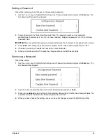
Страница 45: ... Enter After setting the password the computer sets the User Password parameter to Set 4 If desired you can opt to enable the Password on boot parameter 5 When you are done press F10 to save the changes and exit the BIOS Setup Utility Removing a Password Follow these steps 1 Use the w and y keys to highlight the Set Supervisor Password parameter and press the Enter key The Set Password box appears...

Страница 46: ...ing the password the computer sets the User Password parameter to Set 5 If desired you can enable the Password on boot parameter 6 When you are done press F10 to save the changes and exit the BIOS Setup Utility If the verification is OK the screen will display as following The password setting is complete after the user presses Enter If the current password entered does not match the actual curren...

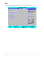
Страница 47: ...used to view or 1 IDE 4 ST9250827AS S1 configure devices 2 IDE CD Optiarc BD ROM BC 5500S S Up and Down arrows 3 PCI BEV MBA v11 0 6 Slot 0900 select a device 4 USB FDC F5 and F6 moves 5 USB KEY the device up or down 6 USB HDD f and r specfies 7 USB CDROM the device fixed or 8 IDE 6 removable Excluded from boot order x exculde or include the device to boot Shift 1 enables or disables a device 1 4 ...

Страница 48: ... S3 by USB plug or unplug Disabled or Enabled Cannot_Find_String Enable or disable the Cannot_Find_String message during boot Disabled or Enabled HIPM Enable or disable Aggressive Link Power Management HIPM Disabled or Enabled SATA FPCI Clock Set the SATA low power control level 133 MHz or 200 MHz SATA Low Power Set SATA low power control type SALP Off Partial on Slumber on or SALP On PhoenixBIOS ...

Страница 49: ...uto AltVid Enable or disable AltVid functionality Disabled or Enabled ASPM L0s L1s Enable or disable Active State Power Management ASPM states for L0s and L1 Disabled or Enabled PCIE Lane Swizzle Enable or disable PCIE Lane Swizzle for PCIE x 16 slot Disabled or Enabled Parameter Description Option ...

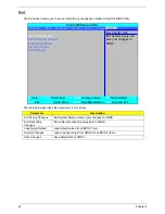
Страница 50: ...o CMOS Load Setup Default Load default values for all SETUP item Discard Changes Load previous values from CMOS for all SETUP items Save Changes Save Setup Data to CMOS PhoenixBIOS Setup Utility Information Main Advanced Security Boot Power Exit Item Specific Help Exit Saving Changes Exit System Setup and Exit Discarding Changes save your changes to Load Setup Defaults CMOS Discard Changes Save Ch...

Страница 51: ... Diskette before you use the Phlash utility NOTE Do not install memory related drivers XMS EMS DPMI when you use the Phlash NOTE Please use the AC adaptor power supply when you run the Phlash utility If the battery pack does not contain enough power to finish BIOS flash you may not boot the system because the BIOS is not completely loaded Fellow the steps below to run the Phlash 1 Prepare a bootab...

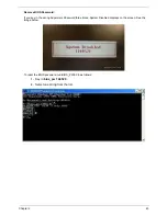
Страница 52: ...ey in the wrong HDD password three times HDD password error code displays See the image below To reset the HDD password run HDD_PW EXE as follows 1 Key in hdd_pw 15494 0 2 Press 2 3 Select one upper case string from the list 4 Reboot system and key in the selected string 0KJFN42 or UVEIQ96 on the HDD User Password screen ...

Страница 53: ...ord If you key in the wrong Supervisor Password three times System Disabled displays on the screen See the image below To reset the BIOS password run BIOS_PW EXE as follows 1 Key in bios_pw 14452 0 2 Select one string from the list ...

Страница 54: ...44 Chapter 2 3 Reboot the system and key in the selected string qjjg9vy 07yqmjd etc for the BIOS user password ...

Страница 55: ...ssemble the computer you need the following tools Wrist grounding strap and conductive mat for preventing electrostatic discharge Flat screwdriver Philips screwdriver Plastic flat screwdriver Plastic tweezers NOTE The screws for the different components vary in size During the disassembly process group the screws with the corresponding components to avoid mismatch when putting back the components ...

Страница 56: ...divided into the following stages External module disassembly Main unit disassembly LCD module disassembly The flowcharts provided in the succeeding disassembly sections illustrate the entire disassembly sequence Observe the order of the sequence to avoid damage to any of the hardware components For example if you want to remove the main board you must first remove the keyboard then disassemble th...

Страница 57: ...that need to be removed during servicing For example if you want to remove the main board you must first remove the keyboard then disassemble the inside assembly frame in that order Screw List Step Screw Quantity Part No MXM Module M2 5 9 4 N A TV Tuner Module M2 3 2 86 ARE07 002 WLAN Module M2 3 2 86 ARE07 002 HDD Module M2 3 2 86 ARE07 002 HDD Carrier M3 0 5 3 5 4 86 A03V7 011 ODD Bracket M2 2 5...

Страница 58: ...Slide the battery lock unlock latch to the unlock position 3 Slide and hold the battery release latch to the release position 1 then slide out the battery pack from the main unit 2 Removing the SD dummy card 1 Push the SD dummy card all the way in to eject it 1 2 ...

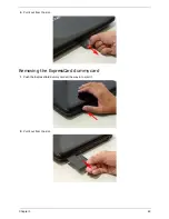
Страница 59: ...Chapter 3 49 2 Pull it out from the slot Removing the ExpressCard dummy card 1 Push the ExpressCard dummy card all the way in to eject it 2 Pull it out from the slot ...

Страница 60: ... Lower Covers 1 See Removing the Battery Pack on page 48 2 Loosen the ten captive screws from the Memory HDD1 and HDD2 Covers 3 Carefully open the memory cover 4 Remove the HDD1 cover as shown HDD2 Cover Memory Cover HDD1 Cover ...

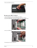
Страница 61: ...he battery See Removing the Battery Pack on page 48 2 Remove the Memory Module cover See Removing the Lower Covers on page 50 3 Push out the release latches on both sides of the DIMM socket to release the DIMM module 4 Remove the DIMM module 5 Repeat steps for the second DIMM module ...

Страница 62: ...ter 3 Removing the MXM Module 1 Remove the battery See Removing the Battery Pack on page 48 2 Remove the four securing screws 3 Grasp the module and remove Step Size Quantity Screw Type MXM Module M2 5 9 NL 4 ...

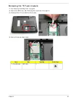
Страница 63: ...1 See Removing the Battery Pack on page 48 2 Remove the HDD2 cover See Removing the Lower Covers on page 50 3 Disconnect the TV Tuner cable from the module 4 Remove the two securing screws Step Size Quantity Screw Type Tv Tuner Module M2 3 NL 2 ...

Страница 64: ...e bracket from the module Removing the WLAN Module 1 Remove the battery See Removing the Battery Pack on page 48 2 Remove the Tv Tuner module See Removing the TV Tuner module on page 53 3 Disconnect the antenna cables from the WLAN board NOTE The following is the correct cable color to connector designation TR1 to Gray and TR2 to Black ...

Страница 65: ...pter 3 55 4 Move the cables to avoid damaging them and remove the two securing screws to release the WLAN board 5 Detach the WLAN board from the WLAN socket Step Size Quantity Screw Type WLAN Module M2 3 2 ...

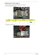
Страница 66: ...ck on page 48 2 Remove the HDD1 cover See Removing the Lower Covers on page 50 3 Remove the two securing screws 4 Use the pull tab to lift up the HDD module to remove NOTE To prevent damage to device avoid pressing down on it or placing heavy objects on top of it Step Size Quantity Screw Type HDD M2 3 2 ...

Страница 67: ...ve the four screws two on each side securing the HDD to the carrier 6 Turn the HDD module upside down and lift the HDD carrier up 7 Remove the connector from the HDD Step Size Quantity Screw Type HDD Carrier M3 0 5 3 5 4 ...

Страница 68: ... Battery Pack See Removing the Battery Pack on page 48 2 Loosen the captive screw securing the ODD module and remove the ODD cap 3 Carefully use a screwdriver to push the locking catch and remove the ODD module 4 Grasp the module and pull out from the main unit ...

Страница 69: ...bracket and remove the ODD bracket from the optical disk drive module 6 Insert a pin in the eject hole of the ODD to eject the ODD tray 7 Press down on the locking catch to release the ODD cover and remove Step Size Quantity Screw Type ODD Bracket M2 2 5 2 ...

Страница 70: ...tch Cover M2 5 3 4 86 T25V7 012 M2 5 6 5 5 86 ARE07 001 Switch Board M2 3 2 86 ARE07 002 Modem Module M2 3 2 86 ARE07 002 LCD Module M2 5 6 5 2 86 ARE07 001 M2 5 6 5 4 86 ARE07 001 M2 5 3 1 86 T25V7 012 Upper Cover M2 5 6 5 11 86 ARE07 001 M2 3 1 86 ARE07 002 M2 5 3 4 86 T25V7 012 Touch Pad Bracket M2 3 4 86 ARE07 002 ...

Страница 71: ...M2 5 6 5 4 86 ARE07 001 eKey Board M2 3 2 86 ARE07 002 Bluetooth Board M2 3 1 86 ARE07 002 Subwoofer M2 5 3 4 86 T25V7 012 ExpressCard Module M2 3 2 86 ARE07 002 Mainboard M2 5 6 5 1 86 ARE07 001 CPU Fan M2 5 6 5 1 86 ARE07 001 Step Screw Quantity Part No ...

Страница 72: ...d to remove the Switch Cover 1 Remove the Battery Pack See Removing the Battery Pack on page 48 2 Locate and remove the nine securing screws as shown 3 Turn the computer over and open the LCD module fully to expose the Switch Cover 4 Lift the Switch Cover up and away Step Size Quantity Screw Type Switch Cover M2 5 3 Blue Callout 4 Switch Cover M2 5 6 5 Red Callout 5 ...

Страница 73: ... the Switch Cover on page 62 2 Lift the locking lever and remove the FFC cable on the left as shown 3 Disconnect both cables on the right as shown 4 Remove the two securing screws from the Switch Board and lift the board clear Step Size Quantity Screw Type Switch Board M2 3 NL 2 ...

Страница 74: ... 1 Remove the Switch Cover See Removing the Switch Cover on page 62 2 Grasp the keyboard and turn it over to expose the FFC cable 3 Lift up the locking lever and remove the FFC cable 4 Remove the keyboard and place it on a clean surface ...

Страница 75: ...ee Removing the Keyboard on page 64 2 Remove the two securing screws 3 Using a plastic pry partially lift up the module to expose the connector 4 While holding the cable in place pull the module away and remove Step Size Quantity Screw Type Modem Module M2 3 NL 2 ...

Страница 76: ...ee Removing the Lower Covers on page 50 3 Remove the Keyboard See Removing the Keyboard on page 64 4 Gently pull the Antenna Cables through the HDD housing 5 Disconnect the MIC and speaker cables IMPORTANT Use tweezers to remove the cable connectors Do not pull on the cable itself to prevent stripping NOTE If you are only removing the LCD module disconnect the MIC cable otherwise disconnect all th...

Страница 77: ...Chapter 3 67 6 Gently pull the MIC cable through the HDD housing 7 Turn the computer on its side and feed the cables through to the upperside 8 Pull the cables completely through ...

Страница 78: ...he WLAN Module on page 54 3 Disconnect the Antenna MIC and Speaker cables See Removing the Antenna MIC and Speaker Cables on page 66 4 Remove the two securing screws from the bottom of the chassis 5 Turn the computer over Use the tweezers to disconnect the LCD interface cable from the chassis Step Size Quantity Screw Type LCD Module M2 5 6 5 2 ...

Страница 79: ... shown 7 Remove the single ground screw and four securing screws two each side connecting the LCD module 8 Carefully remove the LCD module from the chassis Step Size Quantity Screw Type LCD Module M2 5 6 5 NL Red Callout 4 Ground M2 5 3 NL Blue Callout 1 ...

Страница 80: ...e 68 2 Place the computer upside down and remove the remaining eleven screws on the bottom panel 3 Turn the computer over and remove the securing screw from the keyboard plate Step Size Quantity Screw Type Upper Cover M2 5 6 5 11 Step Size Quantity Screw Type DDR Plate M2 3 1 ...

Страница 81: ...late 5 Disconnect the five cables from the mainboard as shown IMPORTANT When removing cables always hold the cable by the pull tab or by the connector Do not pull the cable itself to prevent stripping Disconnect A as shown Release the securing latches and disconnect B as shown A B C D E ...

Страница 82: ...crews from the upper cover Release the securing latches and disconnect C as shown Release the securing latches and disconnect D as shown Release the securing latches and disconnect E as shown Step Size Quantity Screw Type Upper Cover M2 5 3 4 ...

Страница 83: ...ket and pry it open Do not lift the cover completely off NOTE Do not try to pry open more than one edge at a time 8 While holding the cover open pull through any remaining cables 9 Grasp the cover by the opposite edge and lift up to remove the Upper Cover ...

Страница 84: ...e the Upper Cover See Removing the Upper Cover on page 70 2 Disconnect the cable as shown 3 Disconnect the two FFC cables as shown 4 Remove the four securing screw from the Finger Print Reader board Step Size Quantity Screw Type Finger Print Reader M2 3 4 ...

Страница 85: ...Chapter 3 75 5 Remove the bracket from the board 6 Remove the Finger Print Reader board from the Upper Cover ...

Страница 86: ...d 1 Remove the Upper Cover See Removing the Upper Cover on page 70 2 Disconnect the Touch Pad cable from the Touch Pad board IMPORTANT The Touch Pad cannot be removed individually To replace the Touch Pad replace the entire Upper Cover ...

Страница 87: ...per Cover See Removing the Upper Cover on page 70 2 Lift up the locking latch and remove the FFC cable as shown 3 Remove the four screws from the Launch Board 4 Remove the Launch Board from the Upper Cover Step Size Quantity Screw Type Launch Board M2 3 4 ...

Страница 88: ...r Module 1 Remove the Upper Cover See Removing the Upper Cover on page 70 2 Remove four securing screws connecting the Speaker Module 3 Remove the Speaker Module from the upper cover Step Size Quantity Screw Type Speaker Module M2 6 4 ...

Страница 89: ...er Cover See Removing the Upper Cover on page 70 2 Turn the Upper Cover upside down and remove the two securing screws connecting the eKey board 3 Disconnect the eKey Board cable 4 Remove the board as shown Step Size Quantity Screw Type eKey Board M2 3 2 ...

Страница 90: ... Upper Cover See Removing the Upper Cover on page 70 2 Remove the securing screw from the Bluetooth board 3 Disconnect the mainboard to bluetooth cable as shown 4 Disconnect the cable from the mainboard Step Size Quantity Screw Type Bluetooth Board M2 3 1 ...

Страница 91: ...ring screws from the Subwoofer Module 3 Grasp the cable by the end and guide it out of its housing as shown in the following images IMPORTANT The housing guides are hooked to hold the cable in place Do not pull the cable to remove it or damage can occur Step Size Quantity Screw Type Subwoofer Module M2 5 4 4 ...

Страница 92: ...82 Chapter 3 4 Grasp the Subwoofer Module and lift it up to remove ...

Страница 93: ...1 See Removing the Upper Cover on page 70 2 Disconnect the cable connecting the ExpressCard module IMPORTANT Do not grasp the cable itself to prevent fraying 3 Remove the two securing screws Step Size Quantity Screw Type ExpressCard Module M2 3 2 ...

Страница 94: ...84 Chapter 3 4 Lift the ExpressCard module away from the upper cover ...

Страница 95: ...moving the Upper Cover on page 70 2 Disconnect the two cables connected to the motherboard 3 Remove the securing screw from the Mainboard 4 Pull the edge of the lower base outward and lift the motherboard up to remove Step Size Quantity Screw Type Mainboard M2 5 6 5 1 ...

Страница 96: ...d See Removing the Mainboard on page 85 3 Turn the Mainboard right side up and place it on a clean surface 4 Using tweezers grip the cable connector and disconnect the Fan cable from the Mainboard IMPORTANT Do not grip the cable itself to prevent stripping 5 Loosen the four captive screws from the heatsink ...

Страница 97: ...Chapter 3 87 6 Lift the cover to expose the single securing screw Remove the screw 7 Lift the Fan module clear of the Mainboard Step Size Quantity Screw Type CPU Fan Module M2 5 6 5 1 ...

Страница 98: ... Removing the CPU 1 Remove the CPU Fan Module See Removing the CPU Fan Module on page 86 2 Using a flat screwdriver turn the CPU socket latch clockwise 180 to release the CPU k 3 Lift the CPU clear of the Mainboard ...

Страница 99: ...Disassembly Process LCD Module Disassembly Flowchart Screw List Step Screw Quantity Part No LCD Bezel M2 5 6 5 6 86 ARE07 001 Camera Module M2 3 1 86 ARE07 002 LCD Panel M2 5 6 5 6 86 ARE07 001 LCD Brackets M2 3 8 86 ARE07 002 ...

Страница 100: ...e 68 2 Remove the six rubber covers and screws 3 Starting from the inside edges pry the inside of the bezel upwards from the panel Continue moving left until the bezel is removed If necessary use a plastic pry to release the corners of the bezel Step Size Quantity Screw Type LCD Bezel M2 5 6 5 6 ...

Страница 101: ...Chapter 3 91 4 Lift up the bezel and remove it from the LCD Module ...

Страница 102: ...2 Chapter 3 Removing the Inverter Board 1 Remove the LCD Bezel See Removing the LCD Bezel on page 90 2 Disconnect the left and right Inverter board cables as shown 3 Lift up the Inverter Board and remove ...

Страница 103: ...Camera Module 1 Remove the LCD Bezel See Removing the LCD Bezel on page 90 2 Remove the two securing screws from the Camera Module 3 Disconnect the Camera Module cable as shown Step Size Quantity Screw Type Camera Module M2 3 1 ...

Страница 104: ... Bezel See Removing the LCD Bezel on page 90 2 Remove the six securing screws from the LCD Module 3 Disconnect the left and right sides of the Inverter cable 4 Disconnect the Camera Module cable as shown Step Size Quantity Screw Type LCD Panel M2 5 6 5 6 ...

Страница 105: ...Chapter 3 95 5 Grasp the panel by both ends and lift to remove ...

Страница 106: ... See Removing the LCD Panel on page 94 2 Turn the LCD panel over to expose the rear Grip the FPC cable and lift upward to detach the adhesive pads 3 Remove the eight securing screws four on each side from the LCD Panel brackets Step Size Quantity Screw Type LCD Brackets M2 3 8 ...

Страница 107: ...Chapter 3 97 4 Remove the LCD brackets by pulling away from the LCD Panel as shown ...

Страница 108: ...ure Replacing the LCD Panel 1 Align the LCD brackets with the eight screw holes four on each side on the LCD Panel as shown 2 Secure the LCD brackets to the LCD panel 3 Turn the panel over Insert the LCD Panel cable into the LCD Panel as shown ...

Страница 109: ...D Panel cable as shown and press down to secure in place 5 Take care to insert the top of the panel fist and then angle the it in place 6 Place the LCD Panel in the back cover 7 Secure the LCD module with the six securing screws ...

Страница 110: ...100 Chapter 3 8 Connect the left and right Inverter cables 9 Connect the camera cable ...

Страница 111: ...acing the LCD Bezel 1 Starting from the bottom locate the bezel correctly and press down the edges until there are no gaps between the bezel and the LCD Module 2 Replace the six screws and the rubber screw caps provided ...

Страница 112: ...1 Carefully turn the mainboard upside down CPU side up and insert the CPU into the CPU bracket as shown 2 Using a plastic screw driver lock the CPU in the socket as shown 1 Replace the Fan module on the Mainboard 2 Lift the cover to replace the single screw located in the back of the fan module ...

Страница 113: ...Chapter 3 103 3 Tighten the four 4 captive screws on the heatsink 4 Connect the Fan cable to the Mainboard ...

Страница 114: ...ower base outward and insert the motherboard in the lower base 2 Replace the securing screw on the Mainboard 3 Connect the two cables on the mainboard side 1 Insert the module into the alignment pin and press down to secure 2 Connect the Bluetooth cable and replace the securing screw as shown ...

Страница 115: ... cover 2 Replace the two securing screws IMPORTANT The correct location of the ExpressCard Module screws is illustrated in the following image Do not insert the screws in the remaining screw sockets They are locations for upper cover screws 3 Connect the cable connecting the ExpressCard module ...

Страница 116: ...apter 3 Replacing the Subwoofer Module 1 Grasp the Subwoofer Module and insert in the lower base 2 Insert the cables under the housing guide as shown 3 Replace the four securing screws on the Subwoofer Module ...

Страница 117: ...eader 1 Remove the Finger Print Reader board from the Upper Cover 2 Remove the bracket from the board 3 Replace the four securing screw on the Finger Print Reader board NOTE Move back the cabling to allow for easier access to the screw sockets ...

Страница 118: ...108 Chapter 3 4 Connect the two FFC cables as shown 5 Connect the cable as shown ...

Страница 119: ...ORTANT Take note of the eKey button when installing It must face down and the cable connector up in order to install the module correctly 1 Locate and replace the board as shown 2 Connect the eKey Board cable and replace the two securing screws ...

Страница 120: ...y To replace the Touch Pad replace the entire Upper Cover 1 Connect the Touch Pad cable as shown Replacing the Launch Board 1 Replace the Launch Board on the upper cover 2 Replace the four securing screws 3 Insert the FFC flush with the connector and press down on the locking latch to secure ...

Страница 121: ...Reader 1 Replace the Finger Print Reader board on the Upper Cover 2 Replace the bracket on the board 3 Replace the four securing screw on the Finger Print Reader board NOTE Move back the cabling to allow for easier access to the screw sockets ...

Страница 122: ...112 Chapter 3 4 Connect the two FFC cables as shown 5 Connect the cable as shown Replacing the Upper Cover 1 Locate the upper cover over the lower base taking note of the screw sockets ...

Страница 123: ...3 2 Angle the right end of the Upper Cover in place and insert any remaining cables through the lower base as shown 3 Set the Upper Cover down on the lower base 4 Replace the four securing screws on the Upper Cover ...

Страница 124: ...board as shown IMPORTANT When replacing cables always hold the cable by the pull tab or by the connector Do not hold the pull by the cable itself to prevent stripping Connect A as shown Connect B as shown Connect C as shown Connect D as shown A B C D E ...

Страница 125: ...ecuring screw on the keyboard plate 8 Turn the computer upside down and replace the eleven securing screws on the bottom panel to attach the bottom and lower covers Connect E as shown 6 Angle the keyboard plate and insert as shown ...

Страница 126: ... the LCD Module 1 Replace the LCD Module on the Lower Case as shown 2 Replace the single ground screw and four securing screws two each side connecting the LCD module 3 Replace the LCD Interface and back light cables as shown ...

Страница 127: ...ough the Mainboard and are accessible from the underside of lower cover 1 Insert the cabling through the housing as shown 2 Ensure that the cabling is tucked in and secured 3 Turn the computer on its side feed cables through to the underside 4 Turn the computer over and replace the two securing screws ...

Страница 128: ...the computer upside down and insert the MIC and Speaker cables through the HDD housing 5 Take note of the cabling arrangement Ensure that the cabling is secured as shown to prevent damage 6 Connect the MIC and speaker cables ...

Страница 129: ... 3 119 7 Gently pull the Antenna Cables through the HDD housing Replacing the Modem Module 1 Angle the Modem Module as shown and attach to the connector 2 Insert the module and replace the two securing screws ...

Страница 130: ...ing the Keyboard 1 Replace the keyboard cable to the mainboard and secure the locking latch 2 Turn the keyboard over and place the front edge first in the mounting 3 Press down on the areas marked below to secure in place ...

Страница 131: ... 121 Replacing the Switch Board 1 Reseat the Switch Board and replace the two securing screws 2 Connect both cables on the right as shown 3 Replace the FFC cable on the left as shown and close the locking latch ...

Страница 132: ...122 Chapter 3 Replacing the Switch Cover 1 Replace the Switch cover and press down to secure in place 2 Turn the computer over and replace the nine securing screws ...

Страница 133: ...he cover into the tray bottom edge first to secure 2 Turn ODD Module around and secure bracket with two screws 3 Slide Module in chassis and press until Module is flush with chassis 4 Replace the ODD Cap and secure the single captive screw 1 Replace the connector on the HDD 2 Place the HDD in the HDD carrier ...

Страница 134: ...124 Chapter 3 3 Replace the four screws two each side to secure the carrier 4 Insert the HDD left side first and push down to locate the interface correctly 5 Replace the two securing screws ...

Страница 135: ...ard in to the socket 2 Push the board down and replace the two securing screws 3 Replace the two antenna cables NOTE The following is the correct cable color to connector designation TR1 to Gray and TR2 to Black 1 Attach the bracket to the module 2 Insert the TV Tuner board in to the socket ...

Страница 136: ...dules 3 Replace the two securing screws 4 Replace the antenna cable 1 Insert the MXM board in to the socket 2 Replace the four securing screws 1 Insert DIMM in to the socket 2 Press down to locate DIMM correctly 3 Repeat steps 1 and 2 for the second DIMM module ...

Страница 137: ...ing the ExpressCard Dummy Tray 1 Replace the HDD2 cover 2 Replace the HDD1 cover 3 Replace the Memory cover 4 Secure the ten captive screws in the covers 1 Insert the ExpressCard dummy as shown 2 Push into the slot until flush with the chassis cover ...

Страница 138: ...cing the Battery 1 Insert the SD dummy as shown 2 Push into the slot until flush with the chassis cover 1 Slide and hold the battery release latch 1 insert battery in to the main unit 2 2 Slide the battery lock unlock latch to the lock position 1 2 ...

Страница 139: ...ptom to determine which page to go to 4 If the Issue is still not resolved see Online Support Information on page 195 Symptoms Verified Go To Power On Issue Page 130 No Display Issue Page 131 LCD Failure Page 133 Internal Keyboard Failure Page 133 Touch Pad Failure Page 134 Internal Speaker Failure Page 134 Internal Microphone Failure Page 136 ODD Failure Page 138 Rightside USB Failure Page 141 Mo...

Страница 140: ...ove any surge protectors between the computer and the electrical outlet Plug the computer directly into a known good electrical outlet 4 Disconnect the power and open the casing to check the Thermal Unit see Thermal Unit Failure on page 144 and fan airways are free of obstructions 5 Disable the power management settings in the BIOS to ensure they are not the cause of the problem see Boot on page 3...

Страница 141: ... power see Power On Issue on page 130 3 Drain any stored power by removing the power cable and battery and holding down the power button for 10 seconds Reconnect the power and reboot the computer 4 Connect an external monitor to the computer and switch between the internal display and the external display is by pressing Fn F5 on this model If the POST or video appears on the external display see L...

Страница 142: ...he Resolution slider to the desired resolution e Click Apply and check the display Readjust if necessary 6 Roll back the video driver to the previous version if updated 7 Remove and reinstall the video driver 8 Check the Device Manager to determine that The device is properly installed There are no red Xs or yellow exclamation marks There are no device conflicts No hardware is listed under Other D...

Страница 143: ...he following actions one at a time to correct the problem Do not replace a non defective FRUs Built In Keyboard Failure If the built in Keyboard fails perform the following actions one at a time to correct the problem Do not replace a non defective FRUs ...

Страница 144: ...k perform the following actions one at a time to correct the problem Do not replace a non defective FRUs Internal Speaker Failure If the internal Speakers fail perform the following actions one at a time to correct the problem Do not replace a non defective FRUs ...

Страница 145: ...ag the slider to 50 Ensure that the volume is not muted b Click Mixer to verify that other audio applications are set to 50 and not muted 6 Navigate to Start Control Panel Hardware and Sound Sound Ensure that Speakers are selected as the default audio device green check mark NOTE If Speakers does not show right click on the Playback tab and select Show Disabled Devices clear by default 7 Select Sp...

Страница 146: ...d select the Recording tab 2 Right click on the Recording tab and select Show Disabled Devices clear by default 3 The microphone appears on the Recording tab 4 Right click on the microphone and select Enable 5 Select the microphone then click Properties Select the Levels tab 6 Increase the volume to the maximum setting and click OK 7 Test the microphone hardware a Select the microphone and click C...

Страница 147: ...to locate and resolve issues with the computer i When complete click Finish If an issue is discovered follow the onscreen information to resolve the problem 4 Run the Windows Memory Diagnostic Tool For more information see Windows Help and Support 5 Restart the computer and press F2 to enter the BIOS Utility Check the BIOS settings are correct and that CD DVD drive is set as the first boot device ...

Страница 148: ...reaks up or jumps Optical drive not found or not active Not shown in My Computer or the BIOS setup LED does not flash when the computer starts up The tray does not eject Access failure screen displays The ODD is noisy Perform the following general solutions one at a time to correct the problem 1 Reboot the computer and retry the operation 2 Try an alternate disc 3 Navigate to Start Computer Check ...

Страница 149: ... Movie fields select the desired player from the drop down menu 5 Check that the Regional Code is correct for the selected media IMPORTANT Region can only be changed a limited number of times After Changes remaining reaches zero the region cannot be changed even Windows is reinstalled or the drive is moved to another computer a Navigate to Start Control Panel System and Maintenance System Device M...

Страница 150: ...erboard and cable connections c Try an alternate cable if available If the drive works with the new cable the original cable should be replaced 4 Reseat the drive ensuring and all cables are connected correctly 5 Replace the ODD See Disassembly Process on page 46 Drive Read Failure If discs cannot be read when inserted in the drive perform the following actions one at a time to correct the problem...

Страница 151: ... fails perform the following actions one at a time to correct the problem Do not replace a non defective FRUs Modem Function Failure If the internal Modem fails perform the following actions one at a time to correct the problem Do not replace a non defective FRUs ...

Страница 152: ...form the following actions one at a time to correct the problem Do not replace a non defective FRUs EasyTouch Button Failure If the Acer EasyTouch buttons fail perform the following actions one at a time to correct the problem Do not replace a non defective FRUs ...

Страница 153: ...s fail perform the following actions one at a time to correct the problem Do not replace a non defective FRUs Fingerprint Reader Failure If the Fingerprint Reader fails perform the following actions one at a time to correct the problem Do not replace a non defective FRUs ...

Страница 154: ...fails perform the following actions one at a time to correct the problem Do not replace a non defective FRUs HDTV Switch Failure If the HDTV Switch fails perform the following actions one at a time to correct the problem Do not replace a non defective FRUs ...

Страница 155: ...e is not fixed repeat the preceding steps and select an earlier time and date 9 Run the Event Viewer to check the events log for errors For more information see Windows Help and Support 10 Roll back the mouse driver to the previous version if updated recently 11 Remove and reinstall the mouse driver 12 Check the Device Manager to determine that The device is properly installed There are no red Xs ...

Страница 156: ...her a short circuit is suspected or whether the system is inoperative Follow these procedures to isolate the failing FRU do not isolate non defective FRU NOTE Verify that all attached devices are supported by the computer NOTE Verify that the power supply being used at the time of the failure is operating correctly See Power On Issue on page 130 1 Power off the computer 2 Visually check them for d...

Страница 157: ... Determine raw card type PEI chipset MRC 0x12 Find a common CAS latency between the DIMMS and the MCH PEI chipset MRC 0x13 Determine the memory frequency and CAS latency to program PEI chipset MRC 0x14 Determine the smallest common timing value for all DIMMS PEI chipset MRC 0x17 Power management resume PEI chipset MRC 0x18 Program DRAM type DDR2 DDR3 and Power up sequence PEI chipset MRC 0x19 Prog...

Страница 158: ... MRC 0x48 Program TS on Board PEI chipset MRC 0xAF Exit MRC PEI chipset MRC 0xE0 define MEM_ERR_BAD_DIMM S11 PEI chipset MRC 0xE1 define MEM_ERR_ECC_DIMM S06 PEI chipset MRC 0xE2 define MEM_ERR_SIDES S07 PEI chipset MRC 0xE3 define MEM_ERR_WIDTH S08 S10 PEI chipset MRC 0xE4 define MEM_ERR_TRFC FindTrasTrpTrcd PEI chipset MRC 0xE5 define MEM_ERR_CAS_LATENCY S12 S13 PEI chipset MRC 0xE6 define MEM_E...

Страница 159: ...or debug test PPI 1 If install debugTest driver PEI Core 0x22 Debug Test driver for debug test PPI 2 If install debugTest driver PEI Core 0x33 Debug Test driver for debug test PPI 3 If install debugTest driver PEI Core 0x44 Entry point of loadfile PEI Core 0x88 Entry point of apMuLoader PEI Core 0x80 A PEIM found PEI Core 0x82 PEIM not dispatched yet PEI Core 0x84 PEIM satisfies depex PEI Core 0x8...

Страница 160: ...s Recovery Core 0x96 Clear Huge segment Crisis Recovery Core 0x97 Boot Crisis Disk Crisis Recovery Core 0x20 DXE starts DXE Core 0x30 BIOSPSM DXE Core 0x02 BIOSBlockIO DXE Core 0x00 BIOSPSM Exception Handler Divide error BIOSPSM Core 0x38 Cannot locate LegacyRegion DXE BIOSPSM Core 0xB1 ACPISupport driver Installed DXE Core 0xE0 BDS Entry DXE Core 0x07 IA32 variable driver entry DXE Core 0x0D cons...

Страница 161: ... LBT Core 0x33 PDM Post Dispatcher Manager init LBT Core 0x01 IPMI init LBT Core 0xD8 ASF Init LBT Core 0x09 Set in POST flag in CMOS that indicates we are in POST If this bit is not cleared by postClearBootFlagJ AEh the TrustedCore on next boot determines that the current configuration caused POST to fail and uses default values for configuration LBT Core 0x2B Enhanced CMOS init LBT Core 0xE0 EFI...

Страница 162: ...opology and set bridge bus numbers 2 Set the system max bus number 3 Write a 0 to the command register of every PCI device 4 Write a 0 to all 6 base registers in every PCI device 5 Write a 1 to the status register of every PC LBT Core 0xC6 Initialize note dock LBT Core 0xC5 PnPnd dual CMOS optional LBT Core 0x48 Verify that the equipment specified in the CMOS matches the hardware currently install...

Страница 163: ...M fro remote flash LBT Core 0xC6 Initial and install console for UCR LBT Core 0x4E Display copyright notice LBT Core 0xD4 Get CPU branding string LBT Core 0x50 Display CPU type and speed LBT Core 0xC9 pretask before EISA init LBT Core 0x51 EISA Init LBT Core 0x5A Display prompt Press F2 to enter SETUP LBT Core 0x5B Disable CPU cache LBT Core 0x5C Test RAM between 512K and 640K LBT Core 0x60 Determ...

Страница 164: ...ze interrupt controller LBT Core 0x81 Run late device initialization routines LBT Core 0x87 Initialize motherboard configurable devices LBT Core 0x85 Display any ESCD read errors and configure all PnP ISA devices LBT Core 0x82 Test and identify RS232 ports LBT Core 0x84 Test and identify parallel ports LBT Core 0x86 Initialize onboard I O and BDA according to CMOS and presence of external devices ...

Страница 165: ...k indicator Display a message if key switch is locked LBT Core 0xA4 Initialize typematic rate LBT Core 0xDB StrongROM Test LBT Core 0xE2 OEM security key test LBT Core 0xC2 Write PEM errors LBT Core 0xBA Initialize the SMBIOS header and sub structures LBT Core 0xC3 Display PEM errors LBT Core 0xA8 Overwrite the Press F2 for Setup prompt with spaces erasing it from the screen LBT Core 0xAA Scan the...

Страница 166: ...in Extended BDA LBT Core 0x99 Check support status for Self Monitoring Analysis Reporting Technology disk failure warning LBT Core 0xB1 Unload ROM Pilot LBT Core 0xDD Perform remote flash if requested LBT Core 0xC7 If UCR redirection is installed remove display manager and unhook INT10 LBT Core 0XDF Shutdown the PXE UNDI code LBT Core 0xB3 Store enhanced CMOS values in non volatile area LBT Core 0...

Страница 167: ...10 LED2 BATTERY LED 2 CN7 FINGER CONN 11 LED1 SYSTEM LED 3 CN6 TOUCH PAD CONN 12 U1 TRANSFORMER 4 CN8 NEW CARD CONN 13 U2 LAN CHIP 5 CN10 BLUE TOOTH CONN 14 CH1 LCD CONN 6 U17 CARD READER CHIP 15 CN3 SWITCH BOARD CONN 7 U12 EC WINBOND 16 CN2 POWER BOARD CONN 8 U14 BIOS 17 CN4 KEYBOARD CONN 9 U13 AUDIO CHIP Chapter 5 ...

Страница 168: ...N14 FAN CONN 18 CN33 MINI CARD 5 CN15 CRT CONN 19 VR1 VOLUME WHEEL 6 CN16 MXM CONN 20 CN31 CARD READER 7 CN17 HDMI CONN 21 CN26 1st HDD CONN 8 CN18 USB CONN 22 CN19 ODD CONN 9 CN20 USB CONN 23 J1 SODIMM CONN 10 CN29 S PDIF JACK 24 PCN1 BATTERY CONN 11 CN25 MIC CONN 25 T90 CPU SOCKET 12 CN23 LINE IN CONN 26 CN13 RTC SOKET 13 CN27 SPEAKER CONN 27 U24 NVIDIA MCP7 14 CN24 MIC CONN ...

Страница 169: ...OST or when systems enter to BIOS Setup menu However once it is necessary to bypass the password check users need to short the G1 jumper to clear the password To reset the Supervisor and User BIOS passwords perform the following steps Power Off the system and remove the AC power and battery pack from the machine Open the back cover of the machine DDR Thermal Remove the CMOS battery form battery so...

Страница 170: ...r and Battery present If this function is enabled the system will force the BIOS to enter a special BIOS block called Boot Block Steps for BIOS Recovery from USB Storage Before doing this prepare the Crisis USB key The Crisis USB key could be made by executing the Crisis Disk program in another system with Windows XP OS Follow the steps below 1 Save ROM file file name JAL90x64 fd to the root direc...

Страница 171: ...ever reasons a part number change is made it will not be noted on the printed Service Guide For ACER AUTHORIZED SERVICE PROVIDERS your Acer office may have a DIFFERENT part number code from those given in the FRU list of this printed Service Guide You MUST use the local FRU list provided by your regional Acer office to order FRU parts for repair and service of customer machines NOTE To scrap or to...

Страница 172: ...07 001 5 Keyboard KB INT00 478 19 Dummy Express Card N A 6 DDR Cover 33 AR907 001 20 ODD 6M AR907 002 7 Upper Case 60 AS307 001 21 Lower Case 60 AR907 002 8 Power Board Cable 50 AR907 001 22 Power Board 55 ARL07 002 9 Mainboard MB ARL06 001 23 LCD Case 60 ARL07 001 10 Thermal Module 60 ARL07 003 24 Inverter Module 19 TPK07 001 11 VGA Module VG 9MG06 001 25 LCD Panel 6M ARL07 001 12 Memory Door 42 ...

Страница 173: ...NASONIC 6 cell 4400mAh Main COMMON PSS BT 00605 021 Battery SANYO AS 2007B Li Ion 3S2P SANYO 6 cell 4400mAh Main COMMON Normal Type BT 00603 042 Battery SIMPLO AS 2007B Li Ion 3S2P PANASONIC 6 cell 4400mAh Main COMMON PSS BT 00607 016 Battery PANASONIC AS 2007B Li Ion 4S2P PANASONIC 8 cell 4800mAh Main COMMON BT 00805 011 Battery SANYO AS 2007B Li Ion 4S2P SANYO 8 cell 4800mAh Main COMMON BT 00803...

Страница 174: ...8 DANISH 3P 27 A03V7 006 PWR CORD ISR 1 8M 3PBLK FZ0I0008 038 27 TATV7 005 PWR CORD V50CB3T3012180QD TW 110V 3P 27 A99V7 002 POWER CORD SWI 1 8M 3PBLACK FZ010008 011 27 A99V7 004 POWER CORD IT 1 8M 3PBLACK FZ010008 008 27 A99V7 005 POWER CORD S A 1 8M 3BLACK FZ010008 006 27 T48V7 001 POWER CORD US 3PIN ROHS 27 TAXV7 001 POWER CORD EU 1 8M 3PBLACK FM010008 010 27 TATV7 001 POWER CORD UK 1 8M 3PBLAC...

Страница 175: ...ASE W SPEAKER FFC CABLE TP FOR FP 60 AR907 001 LOWER CASE ASSY W SUB WOOF RJ11 W O TV 60 AR907 002 LOWER CASE ASSY W SUB WOOF RJ11 TV OUT CABLE 60 AS307 002 RAM COVER 42 ARL07 001 HDD COVER 1 42 AR907 003 HDD COVER 2ND 42 AR907 004 DDR BRACKET 33 AR907 001 TP BRACKET 33 AR907 002 ODD CAP 42 AR907 007 Category Description Acer Part No ...

Страница 176: ...638 35W Griffin B1 KC TRM02 700 Super Multi Drive DVD RW SUPER MULTI MODULE 6M AR907 002 TOSHIBA Super Multi DRIVE Tray DL 8X TS L633A LF W O bezel SATA KU 00801 021 ODD HLDS Super Multi DRIVE 12 7mm Tray DL 8X GSA T50N LF W O bezel SATA FW RP05 KU 0080D 029 ODD PLDS Super Multi DRIVE 12 7mm Tray DL 8X DS 8A2S LF W O bezel SATA KU 0080F 001 OPTICAL BRACKET 33 AR907 003 ODD BEZEL SUPER MULTI 42 AGW...

Страница 177: ... HDD WD 2 5 5400rpm 160GB WD1600BEVT 22ZCTO ML160 SATA LF F W 11 01A11 KH 16008 022 HDD SEAGATE 2 5 5400rpm 250GB ST9250827AS Corsair SATA LF F W 3 AAA KH 25001 011 HDD TOSHIBA 2 5 5400rpm 250GB MK2546GSX Leo BS SATA I LF F W LB013J KH 25004 001 HDD WD 2 5 IN 5400rpm 250GB WD2500BEVS 22UST0 ML125 SATA LF F W 01 01A01 KH 25008 018 HDD 250GB 5400RPM SATA II HGST HTS542525K9SA00 LF F W C31P KH 25007 ...

Страница 178: ...ack Polish KB INT00 490 Keyboard 17KB FV3 Black Mammoth 106KS Black Norwegian KB INT00 491 Keyboard 17KB FV3 Black Mammoth 105KS Black Korean KB INT00 493 Keyboard 17KB FV3 Black Mammoth 106KS Black Italian KB INT00 494 Keyboard 17KB FV3 Black Mammoth 106KS Black Hungarian KB INT00 497 Keyboard 17KB FV3 Black Mammoth 105KS Black Greek KB INT00 498 Keyboard 17KB FV3 Black Mammoth 106KS Black German...

Страница 179: ...ANTENNA 60 ARL07 001 LCD BEZEL PAINTING FOR CCD 60 AR907 005 LCD BRACKET W HINGE R 33 AR907 006 LCD BRACKET W HINGE L 33 AR907 007 CCD MODULE 0 3M 57 ARE07 001 LCD MODULE 17 1 IN WXGAG IMR HOLO 3D CCD W O ANTENNA 6M ARL07 002 LCD AUO 17 1 WXGA Glare B170PW06 V2 LF 220nit 8ms LK 17105 009 LCD SAMSUNG 17 1 WXGA Glare LTN170BT07 G01 LF 220nit 8ms 500 1 LK 17106 004 INVERTER BOARD 19 TPK07 001 LCD CAB...

Страница 180: ...012 SO DIMM DDRII667 512MB NT512T64UH8B0FN 37C 0 09U NANYA KN 51203 032 Memory MICRON SO DIMM DDRII 667 2GB MT16HTF25664HY 667E1 LF KN 2GB04 001 Memory SAMSUNG SO DIMM DDRII 667 2GB M470T5663QZ3 CE6 LF KN 2GB0B 003 SODIMM 1GB DDRII667 INFINEON HYS64T128021EDL 3S LF KN 1GB02 036 Memory HYNIX SO DIMM DDRII 667 512MB HYMP164S64CP6 Y5 LF KN 5120G 024 MEMORY HYNIX SO DIMM DDRII 667 2GB HYMP125S64CP8 Y5...

Страница 181: ...7 002 RUBBER FOOT 47 AR907 003 RUBBER FOOT LOW 47 AR907 004 Speaker SPEAKER 23 AR907 001 Category Description Part No SCREW M2 5 6 5 86 ARE07 001 SCREW M2 3 86 ARE07 002 SCWER M2 5 3 86 T25V7 012 SCREW M3 0 5 3 5 86 A03V7 011 SCERW M2 2 5 86 A03V7 007 Category Description Acer Part No ...

Страница 182: ...0G 604G50Mi VHP32ATDK1 MC 9MGSHM256CO 2 2G 250 250 6L 5R CB_bg_0 3D_HG_NO13 AAQL60 N AS7530G 704G32Mi EMEA Luxembourg LX ARH0X 039 AS7530G 704G32MiVHP32ATLU1 MC 9MGSHM256CO 2 2G 320 6L 5R CB_bg_0 3D_HG_IT42 ATRM70 N AS7530G 704G32Mi EMEA Sweden Finland LX ARH0X 044 AS7530G 704G32Mi VHP32ATSE1 MC 9MGSHM256CO 2 2G 320 6L 5R CB_bg_0 3D_HG_FI12 ATRM70 N AS7530G 704G32Mi EMEA Holland LX ARH0X 041 AS753...

Страница 183: ...R CB_bg_0 3D_HG_AR13 ATRM70 N AS7530G 703G32Mi EMEA Spain LX ARH0X 078 AS7530G 703G32Mi VHP32ATES1 MC 9MGSHM256CO 2G 1G 320 6L 5R CB_bg_0 3D_HG_ES22 ATRM70 N AS7530G 703G32Mi EMEA Italy LX ARH0X 070 AS7530G 703G32Mi VHP32ATIT1 MC 9MGSHM256CO 2G 1G 320 6L 5R CB_bg_0 3D_HG_IT12 ATRM70 N AS7530G 703G32Mi EMEA Israel LX ARH0X 072 AS7530G 703G32Mi VHP32ATIL1 MC 9MGSHM256CO 2G 1G 320 6L 5R CB_bg_0 3D_HG...

Страница 184: ... CB_bg_0 3D_HG_CS21 ATRM70 N AS7530G 703G32Mi EMEA Czech LX ARH0X 100 AS7530G 703G32Mi VHP32ATCZ2 MC 9MGSHM256CO 2G 1G 320 6L 5R CB_bg_0 3D_HG_SK11 ATRM70 N AS7530G 703G32Mi EMEA Sweden Finland LX ARH0X 099 AS7530G 703G32Mi VHP32ATSE1 MC 9MGSHM256CO 2G 1G 320 6L 5R CB_bg_0 3D_HG_FI12 ATRM70 N AS7530G 703G32Mi EMEA Slovenia Croatia LX ARH0X 083 AS7530G 703G32Mi VHP32ATSI1 MC 9MGSHM256CO 2G 1G 320 6...

Страница 185: ...K11 ATRM70 N AS7530G 703G32Mi EMEA Eastern Europe LX ARH0X 094 AS7530G 703G32Mi VHP32AEU6 MC 9MGSHM256CO 2G 1G 320 6L 5R CB_bg_0 3D_HG_CS21 ATRM70 N AS7530G 703G32Mi EMEA Eastern Europe LX ARH0X 101 AS7530G 703G32Mi VHP32AEU1 MC 9MGSHM256CO 2G 1G 320 6L 5R CB_bg_0 3D_HG_CS21 ATRM70 N AS7530G 703G32Mi EMEA Eastern Europe LX ARH0X 102 AS7530G 703G32Mi VHP32AEU4 MC 9MGSHM256CO 2G 1G 320 6L 5R CB_bg_0...

Страница 186: ... ATRM70 N AS7530G 703G32Mi EMEA Middle East LX ARH0X 062 AS7530G 703G32Mi EM VHP32AME2 MC 9MGSHM256CO 2G 1G 320 6L 5R CB_bg_0 3D_HG_EN15 ATRM70 N AS7530G 703G32Mi EMEA Middle East LX ARH0X 063 AS7530G 703G32Mi EM VHP32AME2 MC 9MGSHM256CO 2G 1G 320 6L 5R CB_bg_0 3D_HG_AR13 ATRM70 N AS7530G 703G32Mi EMEA Turkey LX ARH0X 067 AS7530G 703G32Mi EM VHP32ATR1 MC 9MGSHM256CO 2G 1G 320 6L 5R CB_bg_0 3D_HG_T...

Страница 187: ...S7530G 703G25Mi EMEA Czech LX ARH0X 122 AS7530G 703G25Mi VHP32ATCZ2 MC 9MGSHM256CO 2G 1G 250 BT 6L 5R CB_bg_0 3D_HG_SK11 ATRM70 BT 2 0 AS7530G 604G16Bi EMEA Sweden Finland LX ARH0X 045 AS7530G 604G16Bi VHP32ATSE1 MC 9MGSHM256CO 2 2G 160 6L 5R CB_bg_0 3D_HG_FI12 AAQL60 N AS7530G 703G25Bi EMEA Eastern Europe LX ARH0X 013 AS7530G 703G25Bi VHP32ATEU4 MC 9MGSHM256CO 2G 1G 250 6L 5R CB_bg_0 3D_HG_FI12 A...

Страница 188: ...P32ATDE1 MC 9MGSHM256CO 2G 1G 250 6L 5R CB_bg_0 3D_HG_DE13 ATRM70 N AS7530G 703G25Bi EMEA Belgium LX ARH0X 006 AS7530G 703G25Bi VHP32ATBE1 MC 9MGSHM256CO 2G 1G 250 6L 5R CB_bg_0 3D_HG_NL13 ATRM70 N AS7530G 703G25Bi EMEA Holland LX ARH0X 007 AS7530G 703G25Bi VHP32ATNL1 MC 9MGSHM256CO 2G 1G 250 6L 5R CB_bg_0 3D_HG_NL12 ATRM70 N AS7530G 703G25Bi EMEA Luxembourg LX ARH0X 008 AS7530G 703G25Bi VHP32ATLU...

Страница 189: ... CB_bg_0 3D_HG_EN16 ATRM70 N AS7530G 703G25Bi EMEA South Africa LX ARH0X 002 AS7530G 703G25Bi EM VHP32ATZA1 MC 9MGSHM256CO 2G 1G 250 6L 5R CB_bg_0 3D_HG_FR23 ATRM70 N AS7530G 703G25Bi EMEA Turkey LX ARH0X 026 AS7530G 703G25Bi EM VHP32ATTR1 MC 9MGSHM256CO 2G 1G 250 6L 5R CB_bg_0 3D_HG_TR32 ATRM70 N AS7530G 703G25Bi EMEA Eastern Europe LX ARH0X 012 AS7530G 703G25Bi VHP32ATEU6 MC 9MGSHM256CO 2G 1G 25...

Страница 190: ...TRM70 N AS7530G 704G25Bi EMEA Switzerland LX ARH0X 125 AS7530G 704G25BiVHP32ATCH1 MC 9MGSHM256CO 2 2G 250 6L 5R CB_bg_0 3D_HG_IT42 ATRM70 N AS7530G 704G25Bi EMEA UK LX ARH0X 124 AS7530G 704G25BiVHP32ATGB1 MC 9MGSHM256CO 2 2G 250 6L 5R CB_bg_0 3D_HG_EN14 ATRM70 N AS7530G 704G25Bi EMEA Turkey LX ARH0X 133 AS7530G 704G25Bi EM VHP32ATTR1 MC 9MGSHM256CO 2 2G 250 6L 5R CB_bg_0 3D_HG_TR32 ATRM70 N AS7530...

Страница 191: ...RH0X 144 AS7530G 704G25Bi VHP32ATEU4 MC 9MGSHM256CO 2 2G 250 6L 5R CB_bg_0 3D_HG_FI12 ATRM70 N AS7530G 704G25Bi EMEA Czech LX ARH0X 149 AS7530G 704G25Bi VHP32ATCZ2 MC 9MGSHM256CO 2 2G 250 6L 5R CB_bg_0 3D_HG_SK11 ATRM70 N AS7530G 704G25Bi EMEA Eastern Europe LX ARH0X 147 AS7530G 704G25Bi VHP32ATEU6 MC 9MGSHM256CO 2 2G 250 6L 5R CB_bg_0 3D_HG_CS21 ATRM70 N AS7530G 704G25Bi EMEA South Africa LX ARH0...

Страница 192: ...S 3rd WiFi BG AS7530G 703G32Mi N17WXGA G SO2GBII6 SO1GBII6 N320GB 5 4KS N NSM8XS 3rd WiFi BG AS7530G 703G32Mi N17WXGA G SO2GBII6 SO1GBII6 N320GB 5 4KS N NSM8XS 3rd WiFi BG AS7530G 703G32Mi N17WXGA G SO2GBII6 SO1GBII6 N320GB 5 4KS N NSM8XS 3rd WiFi BG AS7530G 703G32Mi N17WXGA G SO2GBII6 SO1GBII6 N320GB 5 4KS N NSM8XS 3rd WiFi BG AS7530G 703G32Mi N17WXGA G SO2GBII6 SO1GBII6 N320GB 5 4KS N NSM8XS 3rd...

Страница 193: ...rd WiFi BG AS7530G 703G32Mi N17WXGA G SO2GBII6 SO1GBII6 N320GB 5 4KS N NSM8XS 3rd WiFi BG AS7530G 703G32Mi N17WXGA G SO2GBII6 SO1GBII6 N320GB 5 4KS N NSM8XS 3rd WiFi BG AS7530G 703G32Mi N17WXGA G SO2GBII6 SO1GBII6 N320GB 5 4KS N NSM8XS 3rd WiFi BG AS7530G 703G32Mi N17WXGA G SO2GBII6 SO1GBII6 N320GB 5 4KS N NSM8XS 3rd WiFi BG AS7530G 703G32Mi N17WXGA G SO2GBII6 SO1GBII6 N320GB 5 4KS N NSM8XS 3rd Wi...

Страница 194: ...iFi BG AS7530G 703G32Mi N17WXGA G SO2GBII6 SO1GBII6 N320GB 5 4KS N NSM8XS 3rd WiFi BG AS7530G 703G32Mi N17WXGA G SO2GBII6 SO1GBII6 N320GB 5 4KS N NSM8XS 3rd WiFi BG AS7530G 703G32Mi N17WXGA G SO2GBII6 SO1GBII6 N320GB 5 4KS N NSM8XS 3rd WiFi BG AS7530G 703G32Mi N17WXGA G SO2GBII6 SO1GBII6 N320GB 5 4KS N NSM8XS 3rd WiFi BG AS7530G 703G32Mi N17WXGA G SO2GBII6 SO1GBII6 N320GB 5 4KS N NSM8XS 3rd WiFi B...

Страница 195: ...7530G 703G25Bi N17WXGA G SO2GBII6 SO1GBII6 N250GB 5 4KS N NBDCB2XS 3rd WiFi BG AS7530G 703G25Bi N17WXGA G SO2GBII6 SO1GBII6 N250GB 5 4KS N NBDCB2XS 3rd WiFi BG AS7530G 703G25Bi N17WXGA G SO2GBII6 SO1GBII6 N250GB 5 4KS N NBDCB2XS 3rd WiFi BG AS7530G 703G25Bi N17WXGA G SO2GBII6 SO1GBII6 N250GB 5 4KS N NBDCB2XS 3rd WiFi BG AS7530G 703G25Bi N17WXGA G SO2GBII6 SO1GBII6 N250GB 5 4KS N NBDCB2XS 3rd WiFi ...

Страница 196: ...i BG AS7530G 703G25Bi N17WXGA G SO2GBII6 SO1GBII6 N250GB 5 4KS N NBDCB2XS 3rd WiFi BG AS7530G 703G25Bi N17WXGA G SO2GBII6 SO1GBII6 N250GB 5 4KS N NBDCB2XS 3rd WiFi BG AS7530G 703G25Bi N17WXGA G SO2GBII6 SO1GBII6 N250GB 5 4KS N NBDCB2XS 3rd WiFi BG AS7530G 703G25Bi N17WXGA G SO2GBII6 SO1GBII6 N250GB 5 4KS N NBDCB2XS 3rd WiFi BG AS7530G 703G25Bi N17WXGA G SO2GBII6 SO1GBII6 N250GB 5 4KS N NBDCB2XS 3r...

Страница 197: ...i BG AS7530G 704G25Bi N17WXGA G SO2GBII6 SO2GBII6 N250GB 5 4KS N NBDCB2XS 3rd WiFi BG AS7530G 704G25Bi N17WXGA G SO2GBII6 SO2GBII6 N250GB 5 4KS N NBDCB2XS 3rd WiFi BG AS7530G 704G25Bi N17WXGA G SO2GBII6 SO2GBII6 N250GB 5 4KS N NBDCB2XS 3rd WiFi BG AS7530G 704G25Bi N17WXGA G SO2GBII6 SO2GBII6 N250GB 5 4KS N NBDCB2XS 3rd WiFi BG AS7530G 704G25Bi N17WXGA G SO2GBII6 SO2GBII6 N250GB 5 4KS N NBDCB2XS 3r...

Страница 198: ...Fi BG AS7530G 704G25Bi N17WXGA G SO2GBII6 SO2GBII6 N250GB 5 4KS N NBDCB2XS 3rd WiFi BG AS7530G 704G25Bi N17WXGA G SO2GBII6 SO2GBII6 N250GB 5 4KS N NBDCB2XS 3rd WiFi BG AS7530G 703G25Mi N17WXGA G SO2GBII6 SO1GBII6 N250GB 5 4KS N NSM8XS 3rd WiFi BG Model LCD Memory1 Memory2 HDD1 HDD2 ODD WLAN ...

Страница 199: ... are tested under Windows XP Home Windows XP Pro environment Refer to the following lists for components adapter cards and peripherals which have passed these tests Regarding configuration combination and test procedures please refer to the Aspire 7230 7530 7530G series Compatibility Test Report released by the Acer Mobile System Testing Department Appendix B ...

Страница 200: ...535 PANASONIC 6CELL2 2 Battery PANASONIC AS 2007B Li Ion 3S2P PANASONIC 6 cell 4400mAh Main COMMON PSS 60002162 SIMPLO 6CELL2 2 Battery SIMPLO AS 2007B Li Ion 3S2P PANASONIC 6 cell 4400mAh Main COMMON PSS 60001921 SANYO 8CELL2 4 Battery SANYO AS 2007B Li Ion 4S2P SANYO 8 cell 4800mAh Main COMMON 60001535 PANASONIC 8CELL2 4 Battery PANASONIC AS 2007B Li Ion 4S2P PANASONIC 8 cell 4800mAh Main COMMON...

Страница 201: ...827AS Corsair SATA LF F W 3 AAA 60002036 SEAGATE N160GB5 4KS HDD SEAGATE 2 5 5400rpm 160GB ST9160310AS Crockett SATA LF F W 0303 60001922 TOSHIBA DIGI N160GB5 4KS HDD TOSHIBA 2 5 5400rpm 160GB MK1646GSX Leo BS SATA I LF F W LB113J 60002005 HGST SG N160GB5 4KS HDD HGST 2 5 5400rpm 160GB HTS542516K9SA00 Bronco B SATA II LF F W C31P 60002005 HGST SG N160GB5 4KS HDD HGST 2 5 5400rpm 160GB HTS543216L9A...

Страница 202: ...F W C31P 60001994 WD N160GB5 4KS HDD WD 2 5 5400rpm 160GB WD1600BEVT 22ZCTO ML160 SATA LF F W 11 01A11 60002036 SEAGATE N250GB5 4KS HDD SEAGATE 2 5 5400rpm 250GB ST9250827AS Corsair SATA LF F W 3 AAA 60001922 TOSHIBA DIGI N250GB5 4KS HDD TOSHIBA 2 5 5400rpm 250GB MK2546GSX Leo BS SATA I LF F W LB013J 60002005 HGST SG N250GB5 4KS HDD HGST 2 5 5400rpm 250GB HTS542525K9SA00 Bronco B SATA II LF F W C3...

Страница 203: ...emory HYNIX SO DIMM DDRII 667 512MB HYMP164S64CP6 Y5 LF 64 16 0 065um Modem Test 23707801 FOXCONN TW Fox Con MC4Z 1 5_3 3V Foxconn Conexant Unizion 1 5_3 3v T60M955 02 23707801 FOXCONN TW Fox Con MC4Z 1 5_3 3V Aus Foxconn Conexant Unizion 1 5_3 3v AUS T60M955 0x Northbridge Chipset Test 60001915 NVIDIA NVMCP77MH NVIDIA MCP77MH w HDCP EEPROM ODD Test 10001063 SONY NBDCB2XS ODD SONY BD COMBO 12 7mm ...

Страница 204: ...5 ONE TIME VENDER 256M GD2 256M GD2 Wireless Antenna Test 9999995 ONE TIME VENDER PIFA PIFA WLAN Test 23707801 FOXCONN TW 3rd WiFi BG Foxconn FOX_ATH_XB63 Foxconn Atheros XB63 minicard b g 9999995 ONE TIME VENDER 3rd WiFi BG QMI ATH_XB63 Atheros XB63 minicard b g 9999995 ONE TIME VENDER 3rd WiFi BG Foxconn Wireless LAN Broadcom 4312 minicard b g Vendor Type Description ...

Страница 205: ...formation on all of Acer s Notebook Desktop and Server models including Service guides for all models User s manuals Training materials Bios updates Software utilities Spare parts lists TABs Technical Announcement Bulletin For these purposes we have included an Acrobat File to facilitate the problem free downloading of our technical material Also contained on this website are Detailed information ...

Страница 206: ...196 Appendix C ...

Страница 207: ...dicator 10 Core POST Codes 149 CPU 88 D DIMM Module 51 52 Display 4 display hotkeys 14 E EasyTouch Failure 142 Euro 15 ExpressCard Module 83 External Module Disassembly Flowchart 47 F Features 1 Fingerprint Reader Failure 143 Flash Utility 41 FPC Cable 96 FRU Field Replaceable Unit List 161 H Hard Disk Drive1 Module 56 HDTV Switch Failure 144 Hibernation mode hotkey 14 Hot Keys 12 I Indicators 10 ...

Страница 208: ...Core 149 Power On Failure 130 S Speaker Module 78 speakers hotkey 14 System Block Diagram 4 T Test Compatible Components 189 Thermal Unit Failure 144 Top 157 Touch Pad hotkey 14 Touch Pad Bracket 76 Touch Pad Failure 134 Troubleshooting Built in KB Failure 133 EasyTouch Buttons 142 Fingerprint Reader 143 HDTV Switch 144 Internal Microphone 136 Internal Speakers 134 LCD Failure 133 MediTouch Button...

Отзывы: