198
LCD Brackets
96
LCD Failure
133
LCD Module Disassembly
Flowchart
89
LCD Panel
94
lower covers
50
M
Main Unit Disassembly
Flowchart
60
Mainboard
85
media access
on indicator
10
MediaTouch Button Failure
143
Memory Check
130
Model Definition
172
Modem Board
65
Modem Failure
141
N
No Display Issue
131
Notebook Manager
hotkey
14
num lock
on indicator
10
O
ODD Failure
138
Online Support Information
195
optical drive module
58
P
Panel
5
Bottom
9
left
5
PC Card
10
POST Codes
Chipset
147
Core
149
Power On Failure
130
S
Speaker Module
78
speakers
hotkey
14
System
Block Diagram
4
T
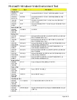
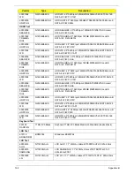
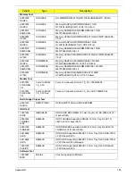
Test Compatible Components
189
Thermal Unit Failure
144
Top
157
Touch Pad
hotkey
14
Touch Pad Bracket
76
Touch Pad Failure
134
Troubleshooting
Built-in KB Failure
133
EasyTouch Buttons
142
Fingerprint Reader
143
HDTV Switch
144
Internal Microphone
136
Internal Speakers
134
LCD Failure
133
MediTouch Buttons
143
Modem
141
No Display
131
ODD
138
Other Failures
145
Power On
130
Thermal Unit
144
Touch Pad
134
USB
141
WLAN
142
TV Tuner Module
53
U
Undetermined Problems
146
USB Failure (Rightside)
141
utility
BIOS
29–41
W
Windows 2000 Environment Test
190
Wireless Function Failure
142
WLAN Board
54
Содержание Aspire 7230
Страница 6: ...VI ...
Страница 10: ...X Table of Contents ...
Страница 54: ...44 Chapter 2 3 Reboot the system and key in the selected string qjjg9vy 07yqmjd etc for the BIOS user password ...
Страница 85: ...Chapter 3 75 5 Remove the bracket from the board 6 Remove the Finger Print Reader board from the Upper Cover ...
Страница 92: ...82 Chapter 3 4 Grasp the Subwoofer Module and lift it up to remove ...
Страница 94: ...84 Chapter 3 4 Lift the ExpressCard module away from the upper cover ...
Страница 101: ...Chapter 3 91 4 Lift up the bezel and remove it from the LCD Module ...
Страница 105: ...Chapter 3 95 5 Grasp the panel by both ends and lift to remove ...
Страница 107: ...Chapter 3 97 4 Remove the LCD brackets by pulling away from the LCD Panel as shown ...
Страница 110: ...100 Chapter 3 8 Connect the left and right Inverter cables 9 Connect the camera cable ...
Страница 113: ...Chapter 3 103 3 Tighten the four 4 captive screws on the heatsink 4 Connect the Fan cable to the Mainboard ...
Страница 118: ...108 Chapter 3 4 Connect the two FFC cables as shown 5 Connect the cable as shown ...
Страница 206: ...196 Appendix C ...

