46
Chapter 3
General Information
Pre-disassembly Instructions
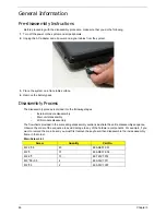
Before proceeding with the disassembly procedure, make sure that you do the following:
1.
Turn off the power to the system and all peripherals.
2.
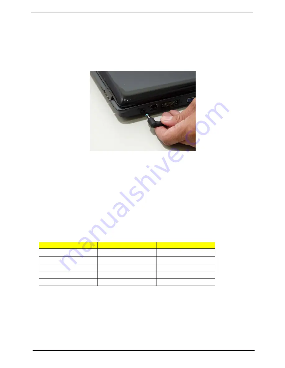
Unplug the AC adapter and all power and signal cables from the system.
3.
Place the system on a flat, stable surface.
4.
Remove the battery pack.
Disassembly Process
The disassembly process is divided into the following stages:
•
External module disassembly
•
Main unit disassembly
•
LCD module disassembly
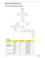
The flowcharts provided in the succeeding disassembly sections illustrate the entire disassembly sequence.
Observe the order of the sequence to avoid damage to any of the hardware components. For example, if you
want to remove the main board, you must first remove the keyboard, then disassemble the inside assembly
frame in that order.
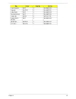
Main Screw List
Screw
Quantity
Part No.
M2.5*6.5
40
86.ARE07.001
M2*3
37
86.ARE07.002
M2.5*3
13
86.T25V7.012
M3*0.5+3.5
4
86.A03V7.011
M2*2.5
2
86.A03V7.007
Содержание Aspire 7230
Страница 6: ...VI ...
Страница 10: ...X Table of Contents ...
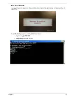
Страница 54: ...44 Chapter 2 3 Reboot the system and key in the selected string qjjg9vy 07yqmjd etc for the BIOS user password ...
Страница 85: ...Chapter 3 75 5 Remove the bracket from the board 6 Remove the Finger Print Reader board from the Upper Cover ...
Страница 92: ...82 Chapter 3 4 Grasp the Subwoofer Module and lift it up to remove ...
Страница 94: ...84 Chapter 3 4 Lift the ExpressCard module away from the upper cover ...
Страница 101: ...Chapter 3 91 4 Lift up the bezel and remove it from the LCD Module ...
Страница 105: ...Chapter 3 95 5 Grasp the panel by both ends and lift to remove ...
Страница 107: ...Chapter 3 97 4 Remove the LCD brackets by pulling away from the LCD Panel as shown ...
Страница 110: ...100 Chapter 3 8 Connect the left and right Inverter cables 9 Connect the camera cable ...
Страница 113: ...Chapter 3 103 3 Tighten the four 4 captive screws on the heatsink 4 Connect the Fan cable to the Mainboard ...
Страница 118: ...108 Chapter 3 4 Connect the two FFC cables as shown 5 Connect the cable as shown ...
Страница 206: ...196 Appendix C ...

