Chapter 5
157
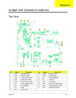
Jumper and Connector Locations
Top View
No.
Jumper
Description
No.
Jumper
Description
1
CN5
MODEM CONN.
10
LED2
BATTERY LED
2
CN7
FINGER CONN.
11
LED1
SYSTEM LED
3
CN6
TOUCH PAD CONN.
12
U1
TRANSFORMER
4
CN8
NEW CARD CONN.
13
U2
LAN CHIP
5
CN10
BLUE TOOTH CONN.
14
CH1
LCD CONN.
6
U17
CARD READER CHIP
15
CN3
SWITCH BOARD CONN.
7
U12
EC WINBOND
16
CN2
POWER BOARD CONN.
8
U14
BIOS
17
CN4
KEYBOARD CONN.
9
U13
AUDIO CHIP
Chapter 5
Содержание Aspire 7230
Страница 6: ...VI ...
Страница 10: ...X Table of Contents ...
Страница 54: ...44 Chapter 2 3 Reboot the system and key in the selected string qjjg9vy 07yqmjd etc for the BIOS user password ...
Страница 85: ...Chapter 3 75 5 Remove the bracket from the board 6 Remove the Finger Print Reader board from the Upper Cover ...
Страница 92: ...82 Chapter 3 4 Grasp the Subwoofer Module and lift it up to remove ...
Страница 94: ...84 Chapter 3 4 Lift the ExpressCard module away from the upper cover ...
Страница 101: ...Chapter 3 91 4 Lift up the bezel and remove it from the LCD Module ...
Страница 105: ...Chapter 3 95 5 Grasp the panel by both ends and lift to remove ...
Страница 107: ...Chapter 3 97 4 Remove the LCD brackets by pulling away from the LCD Panel as shown ...
Страница 110: ...100 Chapter 3 8 Connect the left and right Inverter cables 9 Connect the camera cable ...
Страница 113: ...Chapter 3 103 3 Tighten the four 4 captive screws on the heatsink 4 Connect the Fan cable to the Mainboard ...
Страница 118: ...108 Chapter 3 4 Connect the two FFC cables as shown 5 Connect the cable as shown ...
Страница 206: ...196 Appendix C ...

