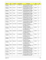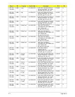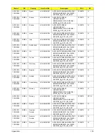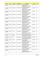
170
Chapter 6
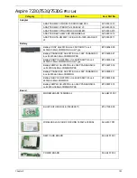
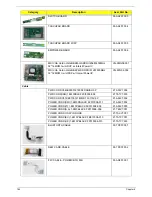
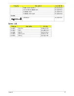
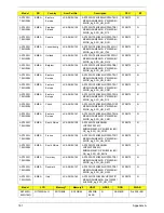
LCD BEZEL PAINTING FOR CCD
60.AR907.005
LCD BRACKET W/HINGE - R
33.AR907.006
LCD BRACKET W/HINGE - L
33.AR907.007
CCD MODULE 0.3M
57.ARE07.001
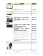
MainBoard
MAINBOARD UMA MCH77MH/GIGALAN W/CARD
READER W/O CPU RAM
MB.ARL06.001
MAINBOARD DIS MCP77MH/GIGALAN W/CARD
READER W/O CPU RAM
MB.ARH06.001
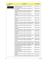
Memory
SO-DIMM DDRII 667 NANYA 1GB NT1GT64U8HB0BN-
3C (0.09U)
KN.1GB03.014
Memory HYNIX SO-DIMM DDRII 667 1GB
HYMP112S64CP6-Y5 LF
KN.1GB0G.012
SO-DIMM DDRII667 512MB NT512T64UH8B0FN-37C
(0.09U)\'NANYA
KN.51203.032
Memory MICRON SO-DIMM DDRII 667 2GB
MT16HTF25664HY-667E1 LF
KN.2GB04.001
Memory SAMSUNG SO-DIMM DDRII 667 2GB
M470T5663QZ3-CE6 LF
KN.2GB0B.003
SODIMM 1GB DDRII667 INFINEON HYS64T128021EDL-
3S LF
KN.1GB02.036
Memory HYNIX SO-DIMM DDRII 667 512MB
HYMP164S64CP6-Y5 LF
KN.5120G.024
MEMORY HYNIX SO-DIMM DDRII 667 2GB
HYMP125S64CP8-Y5 LF
KN.2GB0G.004
Memory SAMSUNG SO-DIMM DDRII 667 1GB
M470T2864QZ3-CE6 LF
KN.1GB0B.016
Heatsink
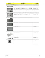
THERMAL MODULE - UMA
60.ARL07.003
THERMAL MODULE - MXM
60.ARL07.004
Miscellaneous
NAME PLATE AS7230
47.ARL07.001
Category
Description
Acer Part No.
Содержание Aspire 7230
Страница 6: ...VI ...
Страница 10: ...X Table of Contents ...
Страница 54: ...44 Chapter 2 3 Reboot the system and key in the selected string qjjg9vy 07yqmjd etc for the BIOS user password ...
Страница 85: ...Chapter 3 75 5 Remove the bracket from the board 6 Remove the Finger Print Reader board from the Upper Cover ...
Страница 92: ...82 Chapter 3 4 Grasp the Subwoofer Module and lift it up to remove ...
Страница 94: ...84 Chapter 3 4 Lift the ExpressCard module away from the upper cover ...
Страница 101: ...Chapter 3 91 4 Lift up the bezel and remove it from the LCD Module ...
Страница 105: ...Chapter 3 95 5 Grasp the panel by both ends and lift to remove ...
Страница 107: ...Chapter 3 97 4 Remove the LCD brackets by pulling away from the LCD Panel as shown ...
Страница 110: ...100 Chapter 3 8 Connect the left and right Inverter cables 9 Connect the camera cable ...
Страница 113: ...Chapter 3 103 3 Tighten the four 4 captive screws on the heatsink 4 Connect the Fan cable to the Mainboard ...
Страница 118: ...108 Chapter 3 4 Connect the two FFC cables as shown 5 Connect the cable as shown ...
Страница 206: ...196 Appendix C ...

