156
Chapter 4
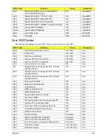
0xB5
Fade out OEM Logo or post string
LBT
Core
0xC5
End hotkey detection (Server BIOS)
LBT
Core
0xBE
If BCP option is enabled, clear the screen before
booting.
LBT
Core
0xB6
If password on boot is enabled, a call is made to
Setup to check password. If the user does not enter
a valid password, Setup does not return.
LBT
Core
0xBC
Clear parity-error latch
LBT
Core
0xB7
Initialize ACPI BIOS.
LBT
Core
0x9B
Enable CPU management (Geyserville I)
LBT
Core
0xBD
Display Boot First menu if MultiBoot is installed and
hotkey pressed.
LBT
Core
0xBF
Check virus and backup reminders.
LBT
Core
0x97
Create pointer to MP table in Extended BDA.
LBT
Core
0x99
Check support status for Self-Monitoring Analysis
Reporting Technology (disk-failure warning).
LBT
Core
0xB1
Unload ROM Pilot
LBT
Core
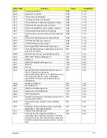
0xDD
Perform remote flash if requested
LBT
Core
0xC7
If UCR redirection is installed, remove display
manager and unhook INT10
LBT
Core
0XDF
Shutdown the PXE UNDI code
LBT
Core
0xB3
Store enhanced CMOS values in non-volatile area
LBT
Core
0xE4
Last Legacy BIOS Task before hand off to UEFI/DXE
LBT
Core
0xB9
Clear all screen graphics before booting.
bootLegacy
Core
0xC0
INT19 entry for legacy boot
bootLegacy
Core
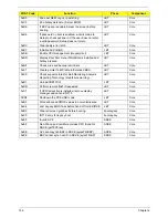
0xEF
Invalid AP #
SDXE
Core
0xEF
Non-Yohna and non-Morem class CPU found for
SDXE (getTSCFreq)
SDXE
Core
0xEE
AP cannot synch BSP in SDXE (syncWithBSP)
SDXE
Core
0xEE
BSP cannot synch w/ AP in SDXE (syncWithAP)
SDXE
Core
POST Code
Function
Phase
Component
Содержание Aspire 7230
Страница 6: ...VI ...
Страница 10: ...X Table of Contents ...
Страница 54: ...44 Chapter 2 3 Reboot the system and key in the selected string qjjg9vy 07yqmjd etc for the BIOS user password ...
Страница 85: ...Chapter 3 75 5 Remove the bracket from the board 6 Remove the Finger Print Reader board from the Upper Cover ...
Страница 92: ...82 Chapter 3 4 Grasp the Subwoofer Module and lift it up to remove ...
Страница 94: ...84 Chapter 3 4 Lift the ExpressCard module away from the upper cover ...
Страница 101: ...Chapter 3 91 4 Lift up the bezel and remove it from the LCD Module ...
Страница 105: ...Chapter 3 95 5 Grasp the panel by both ends and lift to remove ...
Страница 107: ...Chapter 3 97 4 Remove the LCD brackets by pulling away from the LCD Panel as shown ...
Страница 110: ...100 Chapter 3 8 Connect the left and right Inverter cables 9 Connect the camera cable ...
Страница 113: ...Chapter 3 103 3 Tighten the four 4 captive screws on the heatsink 4 Connect the Fan cable to the Mainboard ...
Страница 118: ...108 Chapter 3 4 Connect the two FFC cables as shown 5 Connect the cable as shown ...
Страница 206: ...196 Appendix C ...


