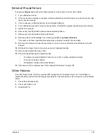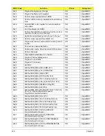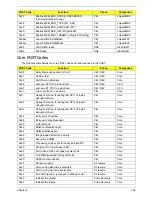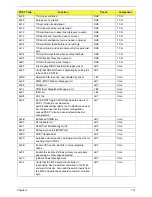
Chapter 5
159
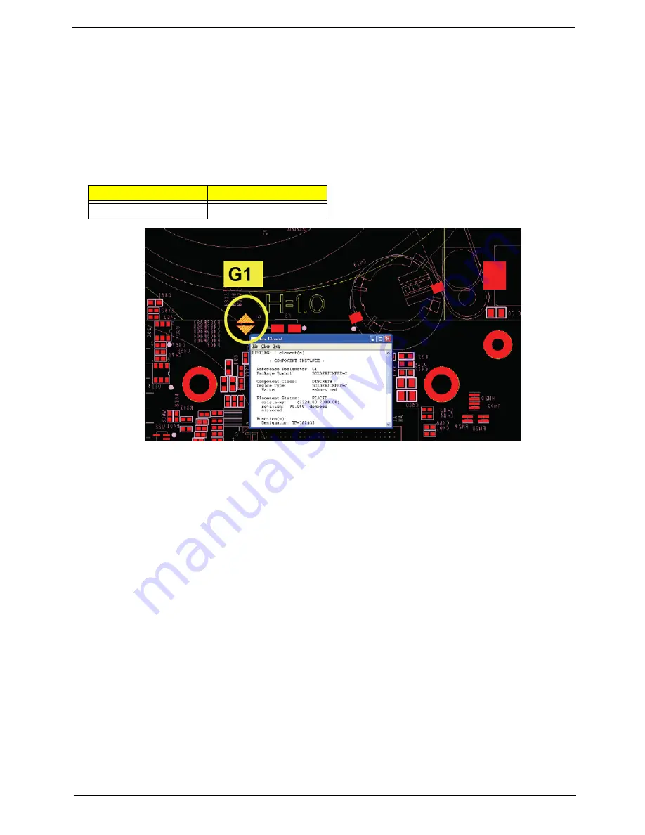
Clearing Password Check and BIOS Recovery
This section provide you the standard operating procedures of clearing password and BIOS recovery for
Aspire 7230/7530/7530G. Aspire 7230/7530/7530G provide one Hardware Open Gap on main board for
clearing password check, and one Hotkey for enabling BIOS Recovery.
Clearing Password Check
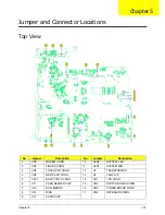
Hardware Open Gap Description
Steps for Clearing BIOS Password Check
If users set BIOS Password (Supervisor Password and/or User Password) for a security reason, BIOS will ask
the password during systems POST or when systems enter to BIOS Setup menu. However, once it is
necessary to bypass the password check, users need to short the G1 jumper to clear the password.
To reset the Supervisor and User BIOS passwords, perform the following steps:
•
Power Off the system and remove the AC power and battery pack from the machine.
•
Open the back cover of the machine (DDR & Thermal)
•
Remove the CMOS battery form battery socket on M/B.
•
Use an electric conductivity tool to short the Short G1 jumper near CMOS battery.
•
Replace the CMOS battery, battery pack, and AC power and start the system.
•
Hit
F2
to enter BIOS and check the passwords are clear.
NOTE:
The steps are only for clearing BIOS Password (Supervisor Password and User Password).
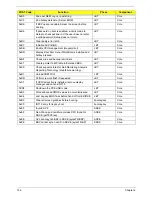
Item
Description
G1
Clear CMOS Jumper
Содержание Aspire 7230
Страница 6: ...VI ...
Страница 10: ...X Table of Contents ...
Страница 54: ...44 Chapter 2 3 Reboot the system and key in the selected string qjjg9vy 07yqmjd etc for the BIOS user password ...
Страница 85: ...Chapter 3 75 5 Remove the bracket from the board 6 Remove the Finger Print Reader board from the Upper Cover ...
Страница 92: ...82 Chapter 3 4 Grasp the Subwoofer Module and lift it up to remove ...
Страница 94: ...84 Chapter 3 4 Lift the ExpressCard module away from the upper cover ...
Страница 101: ...Chapter 3 91 4 Lift up the bezel and remove it from the LCD Module ...
Страница 105: ...Chapter 3 95 5 Grasp the panel by both ends and lift to remove ...
Страница 107: ...Chapter 3 97 4 Remove the LCD brackets by pulling away from the LCD Panel as shown ...
Страница 110: ...100 Chapter 3 8 Connect the left and right Inverter cables 9 Connect the camera cable ...
Страница 113: ...Chapter 3 103 3 Tighten the four 4 captive screws on the heatsink 4 Connect the Fan cable to the Mainboard ...
Страница 118: ...108 Chapter 3 4 Connect the two FFC cables as shown 5 Connect the cable as shown ...
Страница 206: ...196 Appendix C ...

