32
Chapter 2
Advanced
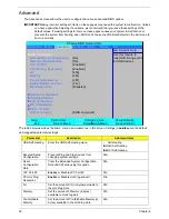
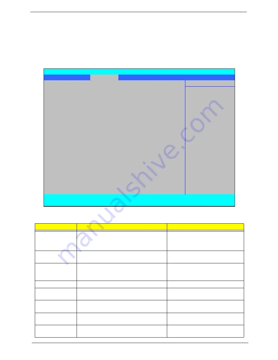
The Advanced screen allows the user to configure the various advanced BIOS options.
IMPORTANT:
Making incorrect settings to items on these pages may cause the system to malfunction. Unless
you have experience adjusting these items, we recommend that you leave these settings at the
default values. If making settings to items on these pages causes your system to malfunction or
prevents the system from booting, open BIOS and choose Load Optimal Defaults in the Exit menu to
boot up normally.
The table below describes the items, menus, and submenus in this screen. Settings in
boldface
are the default
and suggested parameter settings.
Parameter
Description
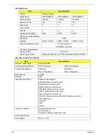
Submenu Items
USB Self-Healing
Enter the USB Self-Healing menu.
•
Self-Healing
X
OCHI Self-Healing
X
EHCI Self-Healing
Secured Setup
Configuration
Prevents Plug and Play devices from
changing system settings.
N/A
Reset
Configuration
Data
Clear the Extended System Configuration
Data (ESCD) area using this option.
N/A
LPC Port 80
Enable
or Disable LPC Port 80.
N/A
PCI Hot-Plug
Resources
Enable
or Disable Hot-Plug support.
N/A
I/O
Set the amount of I/O (in bytes) available to
the Hot-Plug slots.
N/A
Memory
Set the amount of Memory (in bytes)
available to Hot-Plug slots.
N/A
Pre-fetchable
Memory
Set the amount of Pre-fetchable Memory (in
bytes) available to the Hot-Plug slots.
N/A
PhoenixBIOS Setup Utility
Information Main
Advanced
Security
Boot
Power
Exit
Item Specific Help
X
USB Self-Healing
Use this feature to
Secured Setup Configurations:
[No]
tune USB timing event
Reset Configuration Data:
[No]
for USB devices
LPC Port 80:
[Enabled]
PCI Hot-Plug Resources:
[Enabled]
I/O:
[256]
Memory:
[2M]
Pre-fetchable Memory:
[2M]
Enable Multimedia Timer:
[Yes]
W atchdog Timer:
[Disabled]
X
Hammer Configuration
X
Integrated Devices
X
PnP Configuration
X
IDE Configuration
X
iGPU - Chipset
LCD Panel type:
[EDID compliant]
F1
Help
↑↓
Select Item
F5/F6
Change Values
F9
Setup Defaults
ESC
Exit
←→
Select Menu
Enter
Select
X
Sub-Menu
F10
Save and Exit
Содержание Aspire 7230
Страница 6: ...VI ...
Страница 10: ...X Table of Contents ...
Страница 54: ...44 Chapter 2 3 Reboot the system and key in the selected string qjjg9vy 07yqmjd etc for the BIOS user password ...
Страница 85: ...Chapter 3 75 5 Remove the bracket from the board 6 Remove the Finger Print Reader board from the Upper Cover ...
Страница 92: ...82 Chapter 3 4 Grasp the Subwoofer Module and lift it up to remove ...
Страница 94: ...84 Chapter 3 4 Lift the ExpressCard module away from the upper cover ...
Страница 101: ...Chapter 3 91 4 Lift up the bezel and remove it from the LCD Module ...
Страница 105: ...Chapter 3 95 5 Grasp the panel by both ends and lift to remove ...
Страница 107: ...Chapter 3 97 4 Remove the LCD brackets by pulling away from the LCD Panel as shown ...
Страница 110: ...100 Chapter 3 8 Connect the left and right Inverter cables 9 Connect the camera cable ...
Страница 113: ...Chapter 3 103 3 Tighten the four 4 captive screws on the heatsink 4 Connect the Fan cable to the Mainboard ...
Страница 118: ...108 Chapter 3 4 Connect the two FFC cables as shown 5 Connect the cable as shown ...
Страница 206: ...196 Appendix C ...


