Chapter 4
149
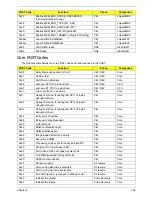
Core POST Codes
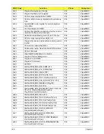
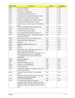
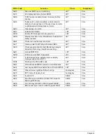
The following table details the core POST codes and functions used in the POST.
0xF3
#define MEM_ERR_RCVEN_FINDCENTER
(CalibrateRcvenForGroup)
PEI
chipset/MRC
0xFZ
#define MEM_ERR_TYPE (S11, S04)
PEI
chipset/MRC
0xF5
#define MEM_ERR_RAWCARD (S11)
PEI
chipset/MRC
0xFA
#define MEM_ERR_SFF (ProgWrioDll)
PEI
chipset/MRC
0xFB
#define MEM_ERR_THERMAL (ProgramThrottling)
PEI
chipset/MRC
0xA0xx
Launch BIOS ACMSclean
PEI
chipset/TXT
0xA4xx
Launch BIOS ACMScheck
PEI
chipset/TXT
0xE5
Wait for ME ready
DXE
HECI/iAMT
0xE6
ME Ready
DXE
HECI/iAMT
POST Code
Function
Phase
Component
0x00
Early Microcode update for CAR
CEI / SEC
Core
0x01
Enable CAR
CEI / SEC
Core
0x02
CAR Done, initial stack
CEI / SEC
Core
0xEE
unknown CPU ID to load uCode
CEI / SEC
CPU
0xEF
unknown DT CPU to load uCode
CEI / SEC
CPU
0xnn
File count found in a volume
PEI
Core
0x11
Debug Test driver for debug test PPI 1 (If install
debugTest driver)
PEI
Core
0x22
Debug Test driver for debug test PPI 2 (If install
debugTest driver)
PEI
Core
0x33
Debug Test driver for debug test PPI 3 (If install
debugTest driver)
PEI
Core
0x44
Entry point of loadfile
PEI
Core
0x88
Entry point of apMuLoader
PEI
Core
0x80
A PEIM found
PEI
Core
0x82
PEIM not dispatched yet
PEI
Core
0x84
PEIM satisfies depex
PEI
Core
0x86
Image loaded but fail on security
PEI
Core
0x88
Executing a PEIM
PEI
Core
0x8A
Processing notify event for newly installed PPI
PEI
Core
0x8C
Handing off to next phase (DXE)
PEI
Core
0x8F
Fail to hand off to next phase, system halt
PEI
Core
0x90
All PEIM dispatched! Going to DxeIpl
PEI
Core
0xCC
AP Micro-code update
PEI
Core
0x20
S3 resume entry
S3 resume
Core
0x21
Start running Boot-time bootscripts
S3 resume
Core
0x22
Start running Run-time bootscripts
S3 resume
Core
0x23
End of S3 resume, jump back to Waking vector
S3 resume
Core
0x80
Initialize the chipset
Crisis Recovery
Core
0x81
Initialize the bridge
Crisis Recovery
Core
POST Code
Function
Phase
Component
Содержание Aspire 7230
Страница 6: ...VI ...
Страница 10: ...X Table of Contents ...
Страница 54: ...44 Chapter 2 3 Reboot the system and key in the selected string qjjg9vy 07yqmjd etc for the BIOS user password ...
Страница 85: ...Chapter 3 75 5 Remove the bracket from the board 6 Remove the Finger Print Reader board from the Upper Cover ...
Страница 92: ...82 Chapter 3 4 Grasp the Subwoofer Module and lift it up to remove ...
Страница 94: ...84 Chapter 3 4 Lift the ExpressCard module away from the upper cover ...
Страница 101: ...Chapter 3 91 4 Lift up the bezel and remove it from the LCD Module ...
Страница 105: ...Chapter 3 95 5 Grasp the panel by both ends and lift to remove ...
Страница 107: ...Chapter 3 97 4 Remove the LCD brackets by pulling away from the LCD Panel as shown ...
Страница 110: ...100 Chapter 3 8 Connect the left and right Inverter cables 9 Connect the camera cable ...
Страница 113: ...Chapter 3 103 3 Tighten the four 4 captive screws on the heatsink 4 Connect the Fan cable to the Mainboard ...
Страница 118: ...108 Chapter 3 4 Connect the two FFC cables as shown 5 Connect the cable as shown ...
Страница 206: ...196 Appendix C ...

