Chapter 2
33
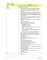
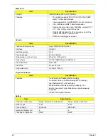
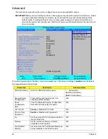
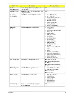
Enable
Multimedia Timer
Enable [
Yes
] or Disable [No] Multimedia
Timer support.
N/A
Watchdog Timer
Disable
or Enable the OS Watchdog Timer
using ACPI WDAT.
N/A
Hammer
Configuration
Enter the Hammer Configuration menu.
•
HT-LDT Frequency
•
HT-LDT Width
•
DDR2 Memory Frequency
•
LS Table loading
•
ISO Flow Control
•
Hi Priority Channel
•
Display Refresh
•
Sync Flood Detection
Integrated
Devices
Enter the Integrated Devices menu.
•
USB Control
•
USB2 Control
•
USB BIOS Legacy Support
•
MAC LAN
•
Azalia Codec
•
Integrated Codec
•
SATA Mode
•
SATA AHCI Mode
•
SATA Hotplug
•
Power on options
•
Interrupt Mode
•
PCI Express MSI
•
S5 WOL
•
Software Based PMU FW
Loading
•
SMU
•
Dynamic Crush Voltage
•
PMU iGPU Stutter Mode
•
PMU System Stutter Mode
•
PMU LMM Mode
•
Dynamic FPCI Clock
PnP Configuration
Enter the PnP Configuration menu.
X
PCI Device, Slot #1
X
PCI/PNP ISA UMB Region
Exclusion
X
PCI/PNP ISA IRQ Resource
Exclusion
IDE Configuration
Enter the IDE Configuration menu.
•
Large Disk Access Mode
•
Local Bus IDE adapter
X
Primary Master
X
Primary Slave
iGPU - Chipset
Enter the iGPU - Chipset menu.
•
Integrated Graphic
•
Video Memory
•
Hybrid Graphics
•
mGPU nPW
•
MXM LVDS/TV
•
MXM CRT/DVI
LCD Panel type
Select the correct LCD panel type for
testing purposes.
N/A
Parameter
Description
Submenu Items
Содержание Aspire 7230
Страница 6: ...VI ...
Страница 10: ...X Table of Contents ...
Страница 54: ...44 Chapter 2 3 Reboot the system and key in the selected string qjjg9vy 07yqmjd etc for the BIOS user password ...
Страница 85: ...Chapter 3 75 5 Remove the bracket from the board 6 Remove the Finger Print Reader board from the Upper Cover ...
Страница 92: ...82 Chapter 3 4 Grasp the Subwoofer Module and lift it up to remove ...
Страница 94: ...84 Chapter 3 4 Lift the ExpressCard module away from the upper cover ...
Страница 101: ...Chapter 3 91 4 Lift up the bezel and remove it from the LCD Module ...
Страница 105: ...Chapter 3 95 5 Grasp the panel by both ends and lift to remove ...
Страница 107: ...Chapter 3 97 4 Remove the LCD brackets by pulling away from the LCD Panel as shown ...
Страница 110: ...100 Chapter 3 8 Connect the left and right Inverter cables 9 Connect the camera cable ...
Страница 113: ...Chapter 3 103 3 Tighten the four 4 captive screws on the heatsink 4 Connect the Fan cable to the Mainboard ...
Страница 118: ...108 Chapter 3 4 Connect the two FFC cables as shown 5 Connect the cable as shown ...
Страница 206: ...196 Appendix C ...


