Chapter 1
23
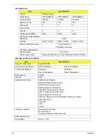
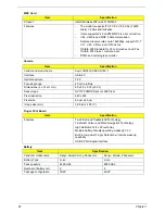
Super-Multi Drive Module
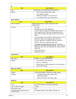
Thermal Sensor Control
BIOS
Item
Specification
Vendor & model name
HLDS/GSA-T50N, Philips DS-8A2S, Toshiba Digi/TS-L633A
Performance Specification
With CD Diskette
With DVD Diskette
Transfer rate (MB/sec)
Sustained:
Max 3.5 Mbytes/sec
Sustained:
Max 10 Mbytes/sec
Buffer Memory
2MB
Interface
SATA
Applicable disc format
Applicable media types:
Writing:
Confirms to DVD+R Version 1.2 and DVD+RW Version 1.3 / DVD+R DL
Version 1.0 /DVD-R Version 2.0 / DVD-RW Version 1.2 / DVD-R DL Version
3.0.
Reading:
DVD single/dual layer (PTP, OTP), DVD-R single/dual layer
DVD+R single/double layer
DVD-RW
DVD+RW
CD-DA
CD-ROM
CD-ROM/XA
Photo-CD, Multi-session, Video CD
CD-I FMV, CD Extra, CD Plus, CD-R, and CD-RW
Loading mechanism
Drawer (Solenoid Open)
Tact SW (Open)
Emergency Release (draw open hole)
Power Requirement
Input Voltage
DC 5 V +/- 5%
Item
Specification
Thermal Sensor Chip
GMT-786 / W83L771
Package
8-pin SSOP
Features
Thermal sensor control Interface
Interface
I
2
C bus, address: 98h
Item
Specification
BIOS vendor
Phoenix BIOS code
BIOS Version
v0.3325 (for MP units)
BIOS ROM type
WND 1MB CMOS Boot Block Flash Memory
BIOS ROM size
1MB
BIOS package
8 pins SOP
Block size
64kbytes per block
Supply Current
•
Active current = 5 mA (Typical)
•
Standby current= 1 µA (Typical)
Содержание Aspire 7230
Страница 6: ...VI ...
Страница 10: ...X Table of Contents ...
Страница 54: ...44 Chapter 2 3 Reboot the system and key in the selected string qjjg9vy 07yqmjd etc for the BIOS user password ...
Страница 85: ...Chapter 3 75 5 Remove the bracket from the board 6 Remove the Finger Print Reader board from the Upper Cover ...
Страница 92: ...82 Chapter 3 4 Grasp the Subwoofer Module and lift it up to remove ...
Страница 94: ...84 Chapter 3 4 Lift the ExpressCard module away from the upper cover ...
Страница 101: ...Chapter 3 91 4 Lift up the bezel and remove it from the LCD Module ...
Страница 105: ...Chapter 3 95 5 Grasp the panel by both ends and lift to remove ...
Страница 107: ...Chapter 3 97 4 Remove the LCD brackets by pulling away from the LCD Panel as shown ...
Страница 110: ...100 Chapter 3 8 Connect the left and right Inverter cables 9 Connect the camera cable ...
Страница 113: ...Chapter 3 103 3 Tighten the four 4 captive screws on the heatsink 4 Connect the Fan cable to the Mainboard ...
Страница 118: ...108 Chapter 3 4 Connect the two FFC cables as shown 5 Connect the cable as shown ...
Страница 206: ...196 Appendix C ...


