162
Chapter 6
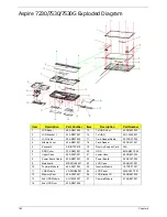
Aspire 7230/7530/7530G Exploded Diagram
Item
Description
Part Number
Item
Description
Part Number
1
LCD Bezel
60.AR907.005
15
1st HDD Door
42.AR907.003
2
LCD Bracket L
33.AR907.007
16
1st HDD
KH.12004.007
3
LCD Cable
50.AR907.002
17
Card Reader Cable
50.TPK07.002
4
Middle Cover
42.AR907.001
18
Card Reader
55.ARL07.001
5
Keyboard
KB.INT00.478
19
Dummy Express Card
N/A
6
DDR Cover
33.AR907.001
20
ODD
6M.AR907.002
7
Upper Case
60.AS307.001
21
Lower Case
60.AR907.002
8
Power Board Cable
50.AR907.001
22
Power Board
55.ARL07.002
9
Mainboard
MB.ARL06.001
23
LCD Case
60.ARL07.001
10
Thermal Module
60.ARL07.003
24
Inverter Module
19.TPK07.001
11
VGA Module
VG.9MG06.001
25
LCD Panel
6M.ARL07.001
12
Memory Door
42.ARL07.001
26
LCD Bracket R
33.AR907.006
13
2nd HDD Module
KH.12004.007
27
Camera Module
57.ARE07.001
14
2nd HDD Door
42.AR907.004
Содержание Aspire 7230
Страница 6: ...VI ...
Страница 10: ...X Table of Contents ...
Страница 54: ...44 Chapter 2 3 Reboot the system and key in the selected string qjjg9vy 07yqmjd etc for the BIOS user password ...
Страница 85: ...Chapter 3 75 5 Remove the bracket from the board 6 Remove the Finger Print Reader board from the Upper Cover ...
Страница 92: ...82 Chapter 3 4 Grasp the Subwoofer Module and lift it up to remove ...
Страница 94: ...84 Chapter 3 4 Lift the ExpressCard module away from the upper cover ...
Страница 101: ...Chapter 3 91 4 Lift up the bezel and remove it from the LCD Module ...
Страница 105: ...Chapter 3 95 5 Grasp the panel by both ends and lift to remove ...
Страница 107: ...Chapter 3 97 4 Remove the LCD brackets by pulling away from the LCD Panel as shown ...
Страница 110: ...100 Chapter 3 8 Connect the left and right Inverter cables 9 Connect the camera cable ...
Страница 113: ...Chapter 3 103 3 Tighten the four 4 captive screws on the heatsink 4 Connect the Fan cable to the Mainboard ...
Страница 118: ...108 Chapter 3 4 Connect the two FFC cables as shown 5 Connect the cable as shown ...
Страница 206: ...196 Appendix C ...

