


5.9
RS-485 interfaces for MODBUS RTU
The device has two RS-485 interfaces for networking via MODBUS RTU:
1. Interface
“
1A (1D+)
”
,
“
1B (1D-)
”
for MODBUS Master applications
•
Pre-programmed function is output from control circuit 1:
|
1. Control signal (2A)
|
e.g. for activating speed controllers for fans or fans with integrated controller and MODBUS
interface (see member MODBUS Master).
The programmable functions correspond to the functions for the analogue outputs described in the
IO Setup.
•
Automatic addressing of members via a patented procedure.
It is no longer necessary to address each individual member manually in the network. The
“
ID
”
connection is also assigned (for more information see the following chapter).
•
Integrated failsafe wiring and 150
Ω
termination.
•
The MODBUS Master interface is galvanically isolated!
2. Interface
“
2A (2D+)
”
,
“
2B (2D-)
”
for MODBUS Slave applications
•
Connection of the device to a superordinate building control system.
•
Setting of address and communication parameters see Programming: Menu group MODBUS
Slave.
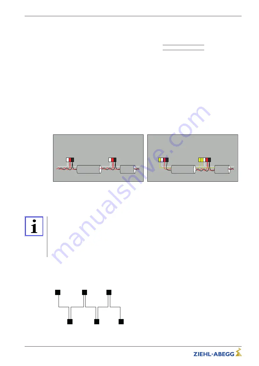
Connection MODBUS Slave and MODBUS Master interface
G
N
D
2
A
(
2
D
+
)
2
B
(
2
D
-)
G
N
D
A
(
D
+
)
B
(
D
-)
CXE / CXG
MODBUS Slave
MODBUS Slave
ID
GN
D
1
A
(
D
+
)
1
B
(
1
D
-)
G
N
D
A
(
D
+
)
B
(
D
-)
CXE / CXG
MODBUS Master
MODBUS Slave
ID
ID
2
ID
1
22.04.2015
v_cxe_modbus_master_idgnd_slave_anschl.vsd
When using telephone cable with four cable cores, we recommend the following allocation:
•
A (D+) = red
•
B (D-) = black
•
ID - ID1/2 = yellow (for automatic addressing for MODBUS Master)
•
GND = white
Information
•
You must ensure correct connection; i.e.
“
A (D+)
”
must also be connected on the following devices
to
“
A (D+)
”
. The same applies to
“
A (D+)
”
.
•
Inaddition,a "GND" connection must be established, as dissimilar potential (over 10 V!) will lead to
the destruction of the RS-485 interface (e.g. lightning).
•
Except for the data link
“
A (D+)
”
,
“
B (D-)
”
, the
“
ID1 - ID2
”
(automatic addressing for MODBUS Master)
and the
“
GND
”
connection, no further cable cores of the data line may be used.
•
Make sure the distance from powerlines and motor wires is suf
fi
cient (min. 20 cm).
The data line must be connected from one device to the next. No other type of wiring is allowed!
Always use only two wires of one lead (twisted pair) for the connection.
MODBUS connection
MODBUS
26.02.2007
v_modbus_verbindung.vsd
Recommended wire types
1. CAT5 / CAT7 cables
2. J-Y (St) 2x2x0.6 (telephone cable)
3. AWG22 (2x2 twisted pair)
Max. allowed wire length 1000 m (CAT5/7 500 m)
Operating Instructions
UNIcon MODBUS Master
Electrical installation
L-BAL-E255-GB 1901 Index 001
Part.-No.
13/121