AFMNA0AA – EPS-BLI HYG – User Manual
Page – 13/75
4.2.4
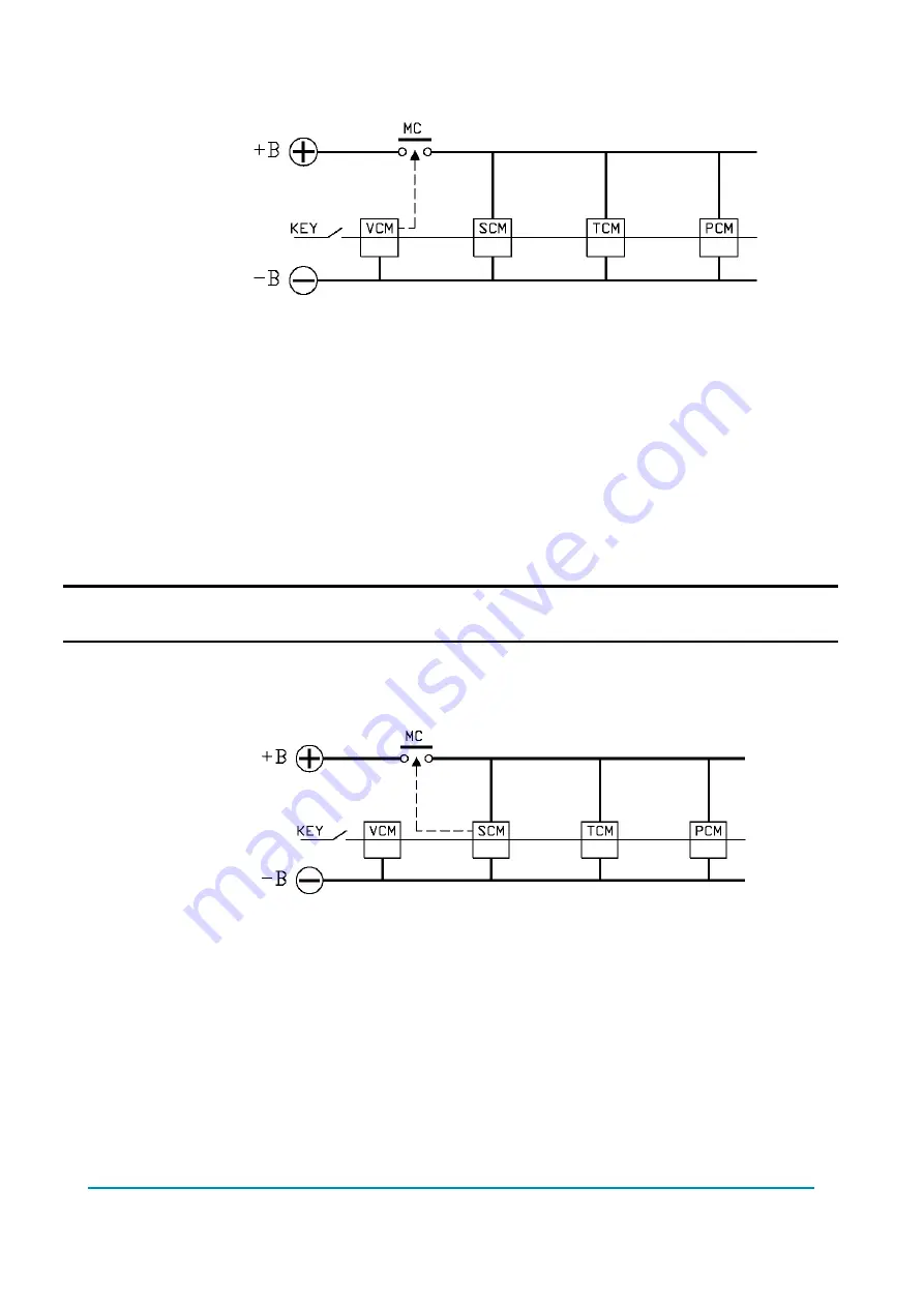
A single MC, driven by the VCM, supplies power rail to all the modules
Figure 4.2.4-1. Single MC driven by the VCM, supplying all the power modules.
This choice is widespread.
Pros:
Cost reduction vs. 4.2.2 (one contactor is saved)
Cons:
An error in the TCM or PCM causes the MC to open. As a consequence, steering
is not allowed during the stopping interval.
To turn operational, SCM needs a waking-up command from the VCM (i.e.
information about MC being closed). This is a safety function to be implemented
in the VCM (i.e. the VCM has to perform a category #3 function, leading to a
redundant and expensive VCM architecture).
U
Chapter 14.2 deals about this safety function to be implemented in the VCM.
See 4.2.1: Bringing TCM to a safe state.
4.2.5
A single MC, driven by the SCM, supplies power rail to all the modules
Figure 4.2.5-1. Single MC driven by the SCM to supply all the power modules.
This choice is a possible alternative to the 4.2.4.
Pros:
Cost reduction vs. 4.2.2 (one contactor is saved)
To turn operational, SCM DOES NOT need a waking-up command from the VCM
because the SCM turns operative as soon as it has closed the MC. A VCM
designed according category#3 is not strictly required.
Cons:
An error in the TCM or PCM causes the MC to open. As a consequence, steering
is not allowed during the stopping interval.
See 4.2.1: Bringing TCM to a safe state.


