


4-18
<4. Measurement Procedures>
IM 80J01A01-01E
4.1.4
Procedures of Setting Stage Heater
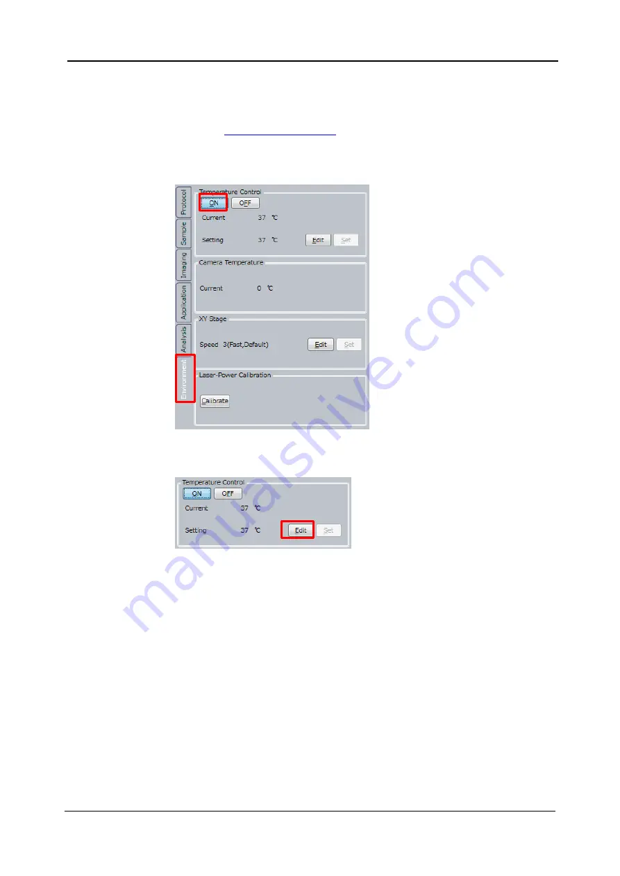
This procedure is only perfomed when controlling environment around
sample. If you
don’t perform environment control, go to procedure
Click
“ON” button in “Environment” window -> “Temperature Control”.
Click
“Edit” button.
Summary of Contents for CQ1
Page 2: ...This document corresponds to the following versions of software Measurement software R1 04 ...
Page 8: ...vi IM 80J01A01 01E Right Side of Utility Box Aperture label ...
Page 24: ......
Page 34: ......
Page 48: ......
Page 177: ... 5 Functions of CQ1 Software 5 81 IM 80J01A01 01E Drag tab to move the window ...
Page 236: ......
Page 238: ......
Page 252: ...7 14 7 Trouble Shooting IM 80J01A01 01E Set sub cover and tighten 2 screws ...
Page 256: ......
Page 266: ......