October 2012
4-32
ColorQube 8570/8870 Service Manual
REP 2.4
Revised, 3rd Revision - Xerox Internal Use Only
Repairs and Adjustments
Replacement
NOTE: For additional tips, refer to the
Drum Assembly Installation
video (also available in the
ColorQube 8570/8870 Training materials).
CAUTION
The Drum Temperature Sensor wiring harness is routed through the Exit Module. Use care
when reinstalling to avoid damaging the sensor.
NOTE: To help seat the Drum properly, steps 2-6 provide an explicit order of placement for
installing the screws to secure the Drum Assembly to the chassis.
1.
Seat the Drum Assembly into the chassis.
2.
Align the screw holes in the left and right sides of the Drum Assembly to the holes in the
chassis sides.
3.
Install 1 screw (metal, T-20) and washer at the rear position on the left side to hold the
Drum Assembly; keep the screw loose.
4.
Install 1 screw (metal, hex-head) and washer at the rear position on the right-side to hold
the Drum Assembly; keep the screw loose.
5.
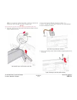
Align the clevis pins on the Transfix Load Arms with the holes in the mounting ears on the
Drum Assembly. The Transfix Load Arms should point in the opposite direction as the
Drum Thermistor. Position the Cam Followers on the Transfix Load Arms under the
Transfix Cams.
6.
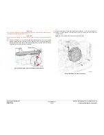
Insert the Clevis Pins through the clevis and the mounting ears on the Drum Assembly
(insert the pins from the outside). Check that the O-ring on each Clevis Pin is inside the
chassis.
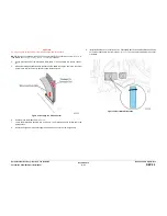
Figure 6 Installing the Transfix Load Arm Clevis Pins
CAUTION
Ensure to move the Spring Cam towards the center of the printer. Applying pressure in the
wrong direction can damage the Transfix Load Module.
CAUTION
Be careful not to pry against the Transfix Cams as shown in
Figure 7
to prevent damaging the
Cam.
7.
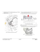
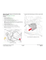
Insert a T-20 Torx bit through the right side slotted hole in the Transfix Load Module.
Engage the hole at the back of the module, and lever the module’s spring cam towards
the center of the printer while connecting the spring hooks to the Transfix Load Arms.
Repeat this process for the left side.
Figure 7 Attaching the Transfix Load Module Arm Cam Springs
8.
Install the bottom screws (metal, T-20), one on each side, keeping them loose.
9.
Install the front screws (metal, hex-head) (with a washer and Ground Plate), one on each
side, keeping the screws loose.
10. Tighten and torque the six screws to 25 in.-lbs. in the following order: first back screws on
both sides, second bottom screws on both sides, and third front screws on both sides.
11.
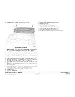
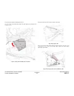
Seat the Exit Module in the chassis by first engaging the 2 front locating pins, and then
the rear locating pins. Connect the Drum Temperature Sensor wiring harness.
NOTE: Rotate the Drum Assembly to verify that the Drum rotates freely. If the Drum is not
rotated freely, check the Drum Maintenance Cam at 6 o’clock position.
Summary of Contents for COLORQUBE 8570
Page 1: ...ColorQube 8570 8870 Printer ColorQube 8570 8870 Service Manual Xerox Internal Use Only...
Page 2: ......
Page 423: ......

