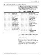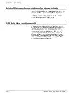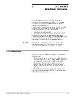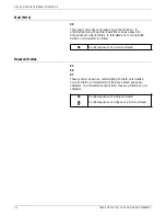
OVERVIEW AND PRINTER SETUP
Configuring the Coax interface card
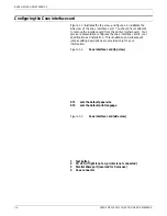
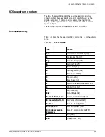
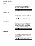
Figure 1-1 illustrates the top view, and figure 1-2 illustrates the
side view of the coax interface card. You should never attempt
to remove the interface card from the printer motherboard. Your
service representative configures the coax interface card to your
specifications at installation. This illustration and subsequent
jumper setting descriptions are provided only for your
information.
Figure 1-1.
Coax interface card (top view)
ST1
sets the default paper size
ST2
sets the default print language
Figure 1-2.
Coax interface card (side view)
1
Test button
2
CU LED (if light is not on, printer is not connected)
3
Parallel share port (reserved for Xerox use)
4
Coax connector
1-6
XEROX MRP FAMILY COAX COMMAND REFERENCE

