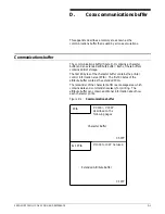
COAX COMMUNICATIONS BUFFER
Printer Output Area
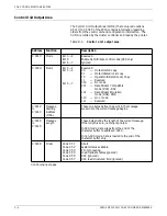
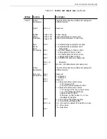
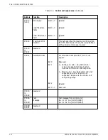
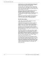
The Printer Output Area (POA) that occupies locations X'0000' to
X'000F' of the Printer Communications Interface Area (PCIA)
contains information regarding printer status and configuration.
The POA is written by the printer and read by the cluster
controller.
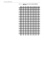
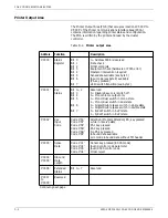
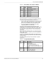
Table D-2. Printer output area
Address
Function
Description
X'0000'
Status
Register
Bit 0
Bit 1
Bit 2
Bit 3
Bit 4
Bit 5
Bit 6
Bit 7
0—Address 0006 is reserved
Data check
Order complete
Equipment check (hardware or PCIA error)
Operator intervention required
Sense data available (see byte 3)
Input code (see byte 2) available
(PA key pressed)
Valid switch transition (see byte 1)
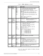
X'0001'
Key
Status
Bit 0—2
Bit 3
Bit 4
Bit 5
Bit 6
Bit 7
Reserved
0—Disable base color switch off
0—Monochrome output only
0—Mono/Dual switch in mono state
1—Mono/Dual switch in dual state
0—Single/Double space switch in single state
1—Single/Double space switch in double state
0—6/8 LPI switch in 6 LPI state
1—6/8 LPI switch in 8 LPI state
X'0002'
Key
Input
Code
Code X'50'
Code X'5F'
Code X'5E'
Code X'5D'
Code X'6B'
Code X'6F'
Attention (Program Attention) PA, key pressed
while in receive state
PA1 key pressed
PA2 key pressed
No PA key pressed
Inbound data available
LU1 mode inbound data without FM header
X'0003'
Sense
Data
Code X'01'
Code X'02'
Code X'03'
Code X'04'
Cancel key pressed (in SCS mode)
Invalid control code parameter
Invalid SCS control code
Order reject
X'0004'
X'0005'
Inbound
Data
Length
X'0006'
Extended
Status
Bit 0—7
Reserved
X'0007
to
X'0009'
Reserved
Continuing next page
D-2
XEROX MRP FAMILY COAX COMMAND REFERENCE

