2 Instrument Configuration
Copyright © WOODLEY EQUIPMENT COMPANY LTD.
68
2. Shake the 7um nominal particles well, and use the 7um nominal particles as a sample for DIFF
testing.
➢
If the resultant scattergram shows a square or diamond with the upper and lower sides
parallel to each other, the device does not need fine-tuning.
➢
If the scattergram shows that the upper and lower sides are not parallel, then take the next
step.
3. If the slanting directional arrow shown in the scattergram is
↗
, then rotate the adjustment knob of
the flow chamber counter-clockwise; if the slanting direction shown in the scattergram is
↘
, then
rotate the adjustment knob of the flow chamber clockwise (the adjustment knob should be lightly
rotated).
4. Use the 7um nominal particles as a sample for DIFF testing.
➢
If the resultant scattergram shows a square or diamond with the upper and lower sides
parallel to each other, the device does not need fine-tuning.
➢
If the scattergram shows that the upper and lower sides are not parallel, then repeat Step 3.
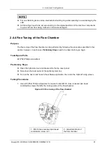
5. After tuning, tighten the two locking screws of the flow chamber, and reinstall the cover panel of
the optical system box as well as the four affixing screws; then lock them in place.
2.4.5 Replacement of High-angle Receiving Plate
Purpose
The high-angle receiving plate can be disassembled and replaced by following the procedures
specified in this section; however, in each case,
Preliminary Steps
need to be taken before you
begin.
Tools/Spare Parts
⚫
#2 (Ph2) Phillips screwdriver
⚫
2.5mm hex-socket screwdriver
⚫
New high-angle receiving plate
Preliminary Steps
1. Turn off the power switch on the left side of the device.
2. Pull out the power cord plug from the rear panel of the device.
3. Open the right-side door and disassemble the top cover panel.
Disassembly
1. Disassemble 2 M3 ×8 stainless steel internal hexagon screws used for fixing the fixed seat of the
side panel card by 2.5mm internal hexagonal wrench, and then remove the fixed seat from the
side basal plate.
2. Pull out 2 connecting wires on the high-angle receiving plate.
3. Disassemble 2 M2.5 ×6 cross recess head screws used for fixing the high-angle receiving plate
by #2
(Ph2) Philips screwdriver, and remove the laser driver plate carefully.

