2 Instrument Configuration
Copyright © WOODLEY EQUIPMENT COMPANY LTD.
7
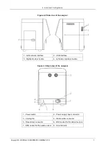
Figure 2-2 Side view of the analyser
1 - LAN network interface
2 - USB interface
3 - Right side door buckle
4 - Left side small door buckle
Figure 2-3 Back view of the analyser
1 - Power switch
2 - Power supply input connector
3 - Cooling fan
4 - Waste outlet connector
5 - Diluent inlet connector
6 - BNC socket for the diluent sensor
7 - BNC socket for the waste sensor
8 - Ground studs


