2 Instrument Configuration
Copyright © WOODLEY EQUIPMENT COMPANY LTD.
36
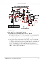
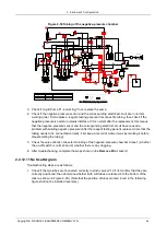
Figure 2-29 WBC tubing for fluid discharge
RBC
WBC
LV3
LV2
LV1
LV4
LV5
LV7
LV9
LV11
LV12
LV15
LV17
LV18
LV6
LV19
250ul 10ml
2.5ml
10ml
2.5ml
J13
T70
T29
T29
T29
J11
J12
T70
T70
T20 T134
T9
J6
J7
J6
J6
J6
J6
J6
T29
J6
J2
T29
T29
T29
T29
T29
J6
J6
T70
Check
valve
T72
T72
J5
J5
T72
J5
J2
T80
T80
T29
T29
T70
T80
T10
T10
T70
T48
T80
T48
T29
J3
J4
T11
T11
T14
J9
P1
T70
T67
T67
T70
One-way
valve
Air Filter
DIFF I
LH
DILU
LH
T237
T115
T70
T13
T70
DIFF I
T214
T15
T14
J1
T70
J3
P2
T80
T29
T70
J3
T80
T80
T80
T80
J3
T70
T171
J4
T29
T69
T28
T211
J3
T80
T80
T168
T29
T164
T197
T165
T80
T29
J3
T29
T29
J8
T105
LV16
LV8
J8
J2
J2
T5
T65
T58
T65
T52
T52
T51
T204
T169
T33
T42
T158
T238
T40
T80
T21
T156
T240
T242
T65
T236
T150
T152
T162
T66
T83
T197
T59
T214
T221
T210
T210
T70
T70
T70
T70
T72
T72
T72
T171
T168
T177
T197
T186
T195
T72
T72
T80
T80
T80
T80
T176
T70
250ul
T80
J3
T80
J3
LV14
LV13
LV10
LV20
LV21
T29
T19
T29
T29
T29
J3
T80
T195
J10
T80
T80
T65
J2
J2
T197
J10
T73
T39
T82
T87
T67
T67
T80
T89
J10
T171
T38
T239
T171
T170
T177
T199
J10
J10
T170
T57
T105
T241
J6
J2
T70
J10
T80
J6
2
3 1
2:COM
1:NC
3:NO
Three-way valve
Tow-way valve
2
1
Note
:
LV-liquid value
;
P-pump
;
T-pipe
;
J-connector
Name
Quantity
Note
Valve
Pump
Syring
21
6
2
2:IN
1:OUT
J3
T43
T26
T65
Negative-
pressure
Sensor
Positive-pressure Sensor
Dual Pipe
Lyse Syringe
SE Sampling
Syringe
V5 DIL
V5 LY2
V5 LY1
If the problem has been resolved, end the procedure; if the problem persists, continue to perform
the following steps:
4. Check whether or not the isolation chamber is airtight.
a. Empty the WBC bath. There are two ways of emptying the WBC bath:
Method I: Go to the
Service
>
Maintenance
>
Maintain
screen, click the
Empty WBC
Bath
button (note that a prompt box will pop up for confirmation after draining; do not
press the
OK
button, otherwise the WBC bath will be refilled with liquid).
Method II: the liquid can be aspirated dry manually using a plastic syringe or other tools.
b. Disassemble the isolation chamber below the WBC bath and pull out the corresponding
tubing. Use the thick No. 50 tube or 1.6mm (i.d.) silicone tube to attach the two connectors to
the side of the isolation chamber, plugging both apertures. Then attach the plastic syringe to
the connector above the isolation chamber using a 1.6mm (i.d.) silicone tube. Push the
plastic syringe to pressurise the isolation chamber, and hold the syringe steady for 30
seconds to check for any appearance of air bubbles. If any air bubbles occur, the isolation
chamber needs to be replaced. See Figure 2-30.


