2 Instrument Configuration
Copyright © WOODLEY EQUIPMENT COMPANY LTD.
47
No.
Tag No.
Description
28
J30
Temperature sensor interface
29
J18
5V power inlet
30
J19
5V power inlet
31
J20
5V power outlet
32
J49
5V power outlet
33
J50
12V power outlet
34
J11
HGB signal interface
35
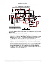
J36
Laser drive panel interface
36
J33
Preamplifier panel signal
interface
37
J10
±12V power inlet
38
J16
110V burning power input
interface
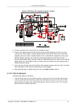
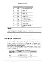
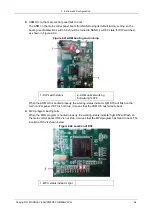
The debugging Interfaces designated for the main control panel are serial interface J7 (RS232
signals), FPGA JTAG interface J3, FPGA AS interface J4, and SD interface for programming before
shipping. Use of these debugging Interfaces is restricted to developers only.
2.3.1.3 Power input and indicator lights on the Main Control Panel
Digital power input and indicator lights
Power input of the digital part is 5V, and it can be tested via testing point TP15 (multimeter shall be
adopted for testing, and during the testing, the red probe shall be connected to TP15, while the black
probe shall be connected to the metal part on the housing). The 5V power input is accompanied by
the fuse F2. Normally the fuse will not be blown since the power supply of the device is equipped
with surge protection. If a short circuit occurs under the input of 5V of power, the power supply will fail
to work properly and a buzzing sound can be heard.
All digital power supplies of the main control panel are equipped with an indicator light and testing
point, and corresponding relationships between the digital power supply, indicator light, and testing
point is shown in the Table 2-2.
Table 2-2 Digital power indicator light
Position Code of
Indicator Light
Meaning
Normal Status
D21
5V digital power supply
On
D17
3.3V digital power supply
On
D16
2.5V digital power supply
On


