waratah FL85 Operator'S Manual Download Page 32

Operation: General

AM24480,000033B -19-29FEB16-1/1

AM24480,000033C -19-29FEB16-1/1

AM24480,000033D -19-06SEP21-1/1

Before starting work

CAUTION: The felling head should only be

operated by individuals who have been properly
trained. Allowing non- or improperly-trained
personnel to operate the machine will increase
the risk of serious injury.

Efficient operation of this felling head is directly informed by
practice and experience. If the felling head is not correctly
adjusted and/or the delimbing knives are not properly
sharpened, the head will not operate to its full potential.

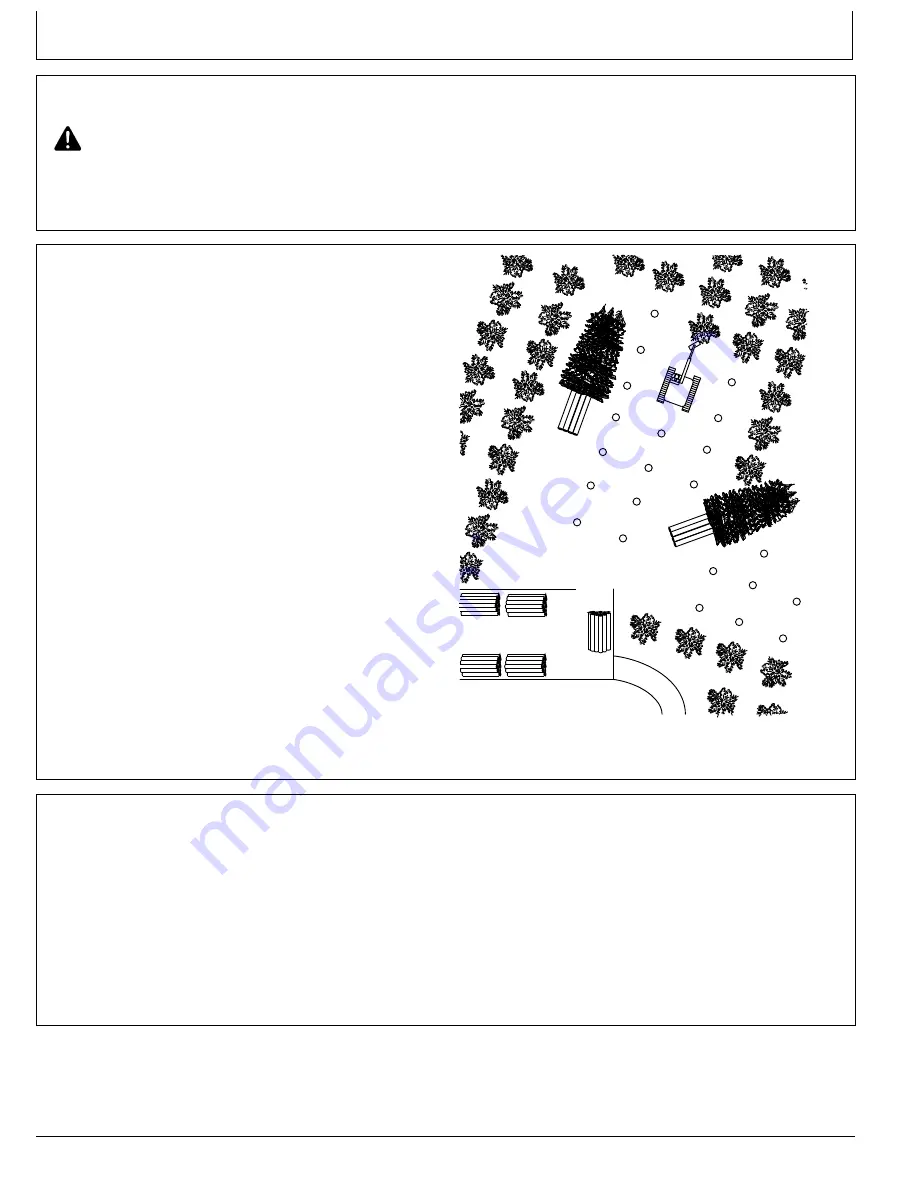
Planning the work area

Mechanised timber felling requires appropriate planning,
the success of which rests upon previous experience.

Establish a management system that includes work site
procedures to limit personnel access during tree felling.

The following elements are important when formulating a
felling plan:

Terrain or area to be harvested

Ground conditions (including: water ways; soil type;
and erosion control)

Tree species

Stem density, stem form, and undergrowth

Site access, roading, and boundaries

Historic sites

Environmental areas

Transmission lines, gas lines, public access, storage
sites, and landings

Staff or team members’ abilities and experience

Hauling distance

Before felling begins, the site must be inspected.
Supervisors should ensure all team members are aware
of the constraints, hazards and requirements of the felling
operation.

Site meetings need to be held regularly, to ensure the
conditions of the plan are being upheld and to address
any elements not accommodated for in the plan.

TX1050356

—UN—29OCT08

Preparation

It is strongly recommended that the operator possesses
previous experience with operating this make of felling
head before starting the felling process.

In addition, before starting felling, it is recommended that:

The carrier is in a good condition, and that all windows
are clean.

You inspect the cutting unit to ensure all its elements
are in good condition (for example, the unit has been
sharpened).

You test all controls.

The carrier’s “automatic idle” function is switched off;
failing to do so may result in the carrier idling down
when the saw chain is in use.

The location of all roads, waterways, and boundaries
have been noted/recorded.

You check for any additional hazards.

You run all functions to ensure the hydraulic functions
have been properly warmed up.

2-1-1

090621

PN=32

Summary of Contents for FL85

Page 1: ...COPYRIGHT 2021 WARATAH NZ LIMITED Tokoroa New Zealand All Rights Reserved LITHO IN NEW ZEALAND Operator s Manual FL85 Felling Head WA115036 06SEP21 ENGLISH...

Page 2: ...red when ordering parts via your local dealer and this information will assist in tracing the machine in the event of theft Warranty is provided as part of Waratah New Zealand Limited s Waratah suppor...

Page 3: ...as and improvements SEND TO Waratah New Zealand Limited PO Box 375 Attn Customer Support Group Tokoroa 3444 New Zealand FAX NUMBER 647 886 0054 Ideas comments Please state page number OVERALL how woul...

Page 4: ...Introduction 090621 PN 4...

Page 5: ...ng a seat belt 1 5 1 Carrier class 1 5 1 Inspecting the carrier 1 5 2 Page Operator Protective Structures OPS 1 5 2 Driving 1 5 2 Processing 1 5 3 Bucking and piling 1 5 3 Safety Signs and labels Head...

Page 6: ...etric cap screw torque values 4 1 4 Miscellaneous Operational checks Operational checks 4 2 1 Miscellaneous Attachment documentation Identification number 4 3 1 Proof of ownership 4 3 1 Miscellaneous...

Page 7: ...ns were as far as we have been able to ascertain correct at the time of publication However we reserve the right to revise any such content without prior notice No part of this publication may without...

Page 8: ...special or for negligence and expressly including any incidental and consequential damages is hereby disclaimed Waratah s obligation to repair or replace shall be the limit of its liability under thi...

Page 9: ...General Information Continued on next page AM24480 0000317 19 26FEB16 1 2 Features TX1044668 11 1 4 5 6 7 8 10 2 3 9 TX1044668 UN 25JUN08 FL85 features 0 1 3 090621 PN 9...

Page 10: ...3 Rotator Hydraulic driven rotation of the felling head 4 Tilt bracket A U shaped bracket that pivots the felling head vertically and horizontally 5 Tilt bracket cylinder This component allows the tr...

Page 11: ...the felling head daily by walking around it Check for any loose or missing hardware Keep all guards and shields in good condition and ensure they are properly installed Repair any identified damage an...

Page 12: ...al and any safety labels if they are missing or damaged T133556 UN 24AUG00 Only operate if qualified Do not operate this felling head unless you have carefully and thoroughly read the Operators Manual...

Page 13: ...apparel equipment at all times Always wear goggles safety glasses to minimise the risk of injury caused by flying pieces of metal or debris Wear close fitting clothing to minimise the risk of serious...

Page 14: ...servicing IMPORTANT Use caution when manoeuvring the felling head close to the carrier failing to exercise caution may result in damage to the carrier and or the felling head XJ1199508 UN 12AUG15 Fell...

Page 15: ...While local safety regulations may vary check with the local authorities to ensure you adhere to all local safety regulations Anticipate a safety zone of at least 5 meters 16 feet between power lines...

Page 16: ...a safe operating distance between the equipment and other personnel Never swing the boom attachment or load over the heads of bystanders 3 Ensure you raise the felling head before moving the vehicle a...

Page 17: ...catcher Always discard saw chain after a chain shot event Use only approved new replacement and repair parts from the same chain or saw manufacturer Keep saw chains sharp and lubricated Follow the saw...

Page 18: ...from a broken saw chain 1 and reduce the whip action that causes a second break of the saw chain ejecting pieces of the cutting saw chain at high speed For additional information about chain shot ref...

Page 19: ...ring back over any portion of the chain shot guard Replace the chain shot guard if any of these condition are present The guard does not maintain its original shape Any perforation is present Any crac...

Page 20: ...chnical Manual If either manual is missing or damaged replace it immediately T133556 UN 24AUG00 Keep personnel off the felling head ALWAYS disable power to the felling head and position the felling he...

Page 21: ...keep vehicles and pedestrians away particularly when you are moving the machine in congested areas or where visibility is restricted Ensure you always keep the signal person in view and coordinate ha...

Page 22: ...it can penetrate the skin causing serious injury Avoid this hazard by relieving pressure before you disconnect hydraulic or other lines and by tightening all connections before applying pressure Never...

Page 23: ...xtreme heat as this may burst the tank accidentally cutting pressurised lines Do not weld or use a torch near a pressurised air tank or line Before you remove the air tank ensure you first relieve pre...

Page 24: ...t the machine on cinder blocks hollow tiles or other props that may crumble under continuous load DO NOT work under a machine that is solely supported by a jack Before starting the service procedure s...

Page 25: ...you will be welding Ensure you only carry out this type of work in well vetilated areas to carry toxic fumes and dust away Ensure you dispose of paint and solvent properly Making welding repairs IMPOR...

Page 26: ...umulator to burst and or the lines to be accidentally cut This can result in the fluid or gas escaping from these components which can in turn result in serious injury To mitigate this risk do not wel...

Page 27: ...addition to wearing your seat belt whenever you operate the machine you should examine the seat belt for any signs of damage and or wear on a regular basis If any part of the seat belt shows evidence...

Page 28: ...sor or owner must always check the cab of the carrier to ensure it is equipped with OPS he or she must also ensure the OPS is not visibly damaged when working in the woods The carrier operator owner o...

Page 29: ...ain shot protection device is installed and has been properly maintained 15 15 15 15 TX1049896 UN 15OCT08 Chain Shot Hazard Zone Bucking and piling When you are using the machine for bucking and or pi...

Page 30: ...Safety Signs and labels AM24480 000037D 19 29FEB16 1 1 Head label positions Series I 000089 XJ1156649 19 04APR14 1 6 1 090621 PN 30...

Page 31: ...Safety Signs and labels AM24480 000037E 19 29FEB16 1 1 Head label positions Series II 000090 KEEP AWAY DANGER KEEP AWAY XJ1199285 19 12AUG15 Head Label Positions 1 6 2 090621 PN 31...

Page 32: ...s Environmental areas Transmission lines gas lines public access storage sites and landings Staff or team members abilities and experience Hauling distance Before felling begins the site must be inspe...

Page 33: ...diameter trees 1 The grapple arms must be able to fit around the butt of the tree 2 Ensure you maintain full control of the felling head at all stages of felling and cutting 3 After you have made a f...

Page 34: ...tails when felling Failing to do can increase the risk of serious injury or death The direction the tree will fall is determined by the position of the felling head on the tree the tree should fall in...

Page 35: ...utts placed so as to facilitate the extraction machine s access from the site pathway This method is dependent upon the finished crop stocking levels Select felling allows a reduction in the number of...

Page 36: ...standing tree can sometimes allow the tree to roll off 6 If a fallen tree becomes hung in another tree be careful when pulling it down Ensure the holding tree is not being pulled in the same directio...

Page 37: ...the saw unit completes a cut the speed of the saw motor will increase and bark chips may be visible 7 The saw will return automatically once you complete a cut and stop activating the saw button 8 Yo...

Page 38: ...rees consecutively on the right and left this reduces the amount of carrier movement and ensures the stacks are positioned to facilitate stem lifting Plantation out row Full tree felling Similar to th...

Page 39: ...which the tree falls which in turn prevents damage caused by the tree moving forward and down Position the felling head so it is located at the front or in the desired fall direction of the tree Then...

Page 40: ...cuts will prevent the tree from snapping off too soon You can use this method in any situation where you require greater felling control such as with large butt flares heavy leaners badly swept 2 1 TX...

Page 41: ...c hose 6 Saw motor swivel 7 Bar holder 8 Saw bar 1 The saw unit is equipped with a lubrication oil pump which is integrated with the feed out cylinder During the feed out process the lubrication oil p...

Page 42: ...dures on items at multiples of the original requirement For example at 500 hours where applicable you should also service those items listed under 250 hours 125 hours 10 hours or daily Record keeping...

Page 43: ...s or signs of excessive wear Monthly Every 200 250 Hours Complete the weekly schedule Clean and inspect the saw bar Check and inspect the tilt bracket pins and bushings Torque the saw mounting cap scr...

Page 44: ...bar It should take approximately 1 5 seconds for the saw bar to retract from its full out position if retraction is too slow or too fast check the air pressure Ensure the air pressure does not exceed...

Page 45: ...79 kPa 13 8 bar 200 psi 4 Remove the air pump nozzle from the valve 5 Re install the small air inlet cap 6 Re install the large air inlet cap IMPORTANT Ensure you replace both inlet caps properly debr...

Page 46: ...pressed air 4 Re install the small inlet cap 3 5 Re install large air inlet cap 2 IMPORTANT Ensure you replace both inlet caps properly debris can build up in the air inlet allowing air to leak from t...

Page 47: ...m stalling out 1 Close the grapple arms 2 Place the felling head in the tilt up position securely on the ground 3 Shut down the carrier CAUTION As the felling head can move or function unexpectedly yo...

Page 48: ...aced securely on flat level ground Failing to follow this process can increase the risk of serious injury or death 10 Remove the gauge 5 4 5 TX1045004 UN 02JUL08 4 Saw bar travel port 5 Gauge 11 Re in...

Page 49: ...top the engine turn off any master shut offs and do not allow personnel in the cab CAUTION To reduce the risk of injury when working on or with the saw chain ensure you wear the correct safety gloves...

Page 50: ...brication fittings Depending on the working conditions you should lubricate the felling head at least once a week via all 19 lubrication points 1 Upper link x3 lubrication fittings 2 Tilt frame x2 lub...

Page 51: ...loosen tighten the chain as required Hydraulic hoses Ensure you inspect the hydraulic hoses and their associated fasteners for signs of damage and for any evidence of leaking you should complete this...

Page 52: ...are tightened appropriately and do not show signs of damage and or excessive wear If these fasteners are loose or there are signs of damage and or wear tighten repair or replace them as required 1 Li...

Page 53: ...e bar holder 2 connecting the ring on the lever 9 to the pin 1 and connecting the hook 11 to the pin 7 4 Pull the lever 9 to compress the tensioning device When the bar holder 2 is in the correct posi...

Page 54: ...and remove the saw chain when making any adjustments or servicing the saw unit 1 Place the unit so it rests securely on the ground with the saw unit facing up 2 Remove the saw chain from the unit Ref...

Page 55: ...on and maintenance as other parts of the saw unit NOTE A worn saw chain sprocket may cause damage to the saw bar or to the saw chain If the saw chain sprocket has been damaged it cannot be repaired it...

Page 56: ...85 210 360 265 285 210 360 265 730 540 920 680 1030 760 1300 960 1 1 8 400 300 510 375 400 300 510 375 910 670 1150 850 1450 1075 1850 1350 1 1 4 570 420 725 535 570 420 725 535 1280 945 1630 1200 205...

Page 57: ...insert or crimped steel type lock nuts to approximately 50 per cent of the dry torque shown in the chart and tighten toothed or serrated type lock nuts to the full torque vale The torque value should...

Page 58: ...1580 1160 2000 1475 M30 660 490 850 625 1290 950 1630 1200 1850 1350 2300 1700 2140 1580 2700 2000 M33 900 665 1150 850 1750 1300 2200 1625 2500 1850 3150 2325 2900 2150 3700 2730 M36 1150 850 1450 10...

Page 59: ...resulting in injury DO NOT use these values if a different torque value or tightening procedure is given for a specific application The torque values listed are for general use only Ensure you check t...

Page 60: ...complete all the necessary visual inspections Be aware that for many of the checks the machine must be at the correct operating temperature 1 FL85 operational checks 1A The saw motor rotates backwards...

Page 61: ...1F The felling head drops a load unexpectedly The hydraulic pressure is too low YES Replace the hose s as needed YES Check the hydraulic pressure YES Check the piston seal NO Perform the next check NO...

Page 62: ...Check the lubrication system YES Adjust the chain tension pressure YES Bleed the tension system NO Perform the next check NO Perform the next check The chain lubrication malfunctions NO Contact your l...

Page 63: ...al authorised dealer The swivel seal rings are damaged 1L There is oil leaking from the saw The saw is damaged YES Replace all the swivel seal rings YES Replace the damaged parts YES Replace the pisto...

Page 64: ...del Number Serial Number Proof of ownership To ensure you can provide appropriate proof of ownership Maintain an up to date inventory of all product and component serial numbers and store this in a se...

Page 65: ...ollow this process can increase the risk of serious injury or death CAUTION When you are filling the oil tank ensure you stand away from any moving parts the saw bar and the grapple arms can move unex...

Page 66: ...ead length F Felling head width G Upper length width Item Measurement Specification FL85 Felling Head A Height from the centre of the upper link pin to the center of the lower link pin 380 mm 14 96 B...

Page 67: ...mm 33 5 Type of chain tension Automatic Type of chain lubrication Proportional Type of head rotation Continuous Hydraulic pressure and flow Grapple pressure 24 821 kPa 248 bar 3600 psi Grapple open t...

Page 68: ...E Felling head length F Felling head width G Upper length width Item Measurement Specification FL85 Series II A Height from the centre of the upper link pin to the centre of the lower link pin 380 mm...

Page 69: ...cation Proportional Type of felling head rotation Continuous Hydraulic pressure and flow Saw unit pressure See saw unit F12 40 Saw unit flow rate See saw unit F12 40 Grapple pressure 19 000 kPa 190 ba...

Page 70: ...Measurement Specification F12 40 Saw A Height without the saw motor 206 mm 8 11 B Total height 333 mm 13 10 C Total length 650 5 mm 25 60 D Length to the centre of the shaft 475 5 mm 18 70 E Total wi...

Page 71: ...rate 172 256 L min 45 67 gpm Chain tensioning pressure 4 500 5 700 kPa 45 57 bar 650 825 psi Bar travel pressure 5 000 5 500 kPa 50 55 bar 725 800 psi Maximum saw chain speed Refer to the manufacture...

Page 72: ...sure Pounds per square inch psi Unit Symbol Volume Cubic millimeter mm3 m3 Cubic inch cu in Millilitre mL Litre L Cubic metre cm3 Pint pt Quart qt Gallon U S gal Mass Gram g Kilogram kg Ton metric t T...

Page 73: ...Area sq mile x 2 59 sq km acres x 0 00405 sq km acres x 0 4047 hectares sq yards x 0 8361 sq m sq feet x 0 0929 sq m sq inches x 6 452 sq cm sq inches x 645 2 sq mm sq km x 0 3861 sq miles sq km x 24...

Page 74: ...x 0 2964 in of Hg MPa x 145 psi atm x 14 70 psi bar x 14 50 psi Flow Flow U S gpm x 3 790 litres min U S gpm x 0 063 litres sec cu ft min x 0 472 litres sec litres sec x 0 264 U S gpm litres sec x 15...

Page 75: ...eet x 144 0 cu in BTU x 778 0 lb ft bushel x 1 244 cu ft cu ft x 17280 cu in cu ft x 7 481 U S gallon U S gallon x 231 0 cu in HP x 33 000 lb ft min HP x 0 7457 kilowatt kilowatt x 1 341 HP knot x 1 1...

Page 76: ...1 4 264 2 832 600 0 276 0 234 1 0 664 138 0 415 0 353 1 506 1 208 2 1 67 7 25 4 81 1000 The apparent volume is measured by the cord column A and cubic metres stacked column C values while the solid vo...

Page 77: ...3 2 4 Depressurize air tank 3 2 3 Maintenance miscellaneous Replace saw bar 3 4 2 Replace saw chain 3 4 1 Replace saw chain sprocket 3 4 3 Miscellaneous Additional metric cap screw torque values 4 1...

Page 78: ...General safety 1 2 1 General safety precautions 1 2 2 Page Operating precautions 1 2 4 Operational safety 1 2 3 Recognize safety information 1 2 4 Safety maintenance precautions Make welding repairs s...

Page 79: ...Index Index 3 090621 PN 79...

Page 80: ...Index Index 4 090621 PN 80...

Reviews: