Force Imaging
Force Calibration Mode
178
MultiMode SPM Instruction Manual
Rev. B
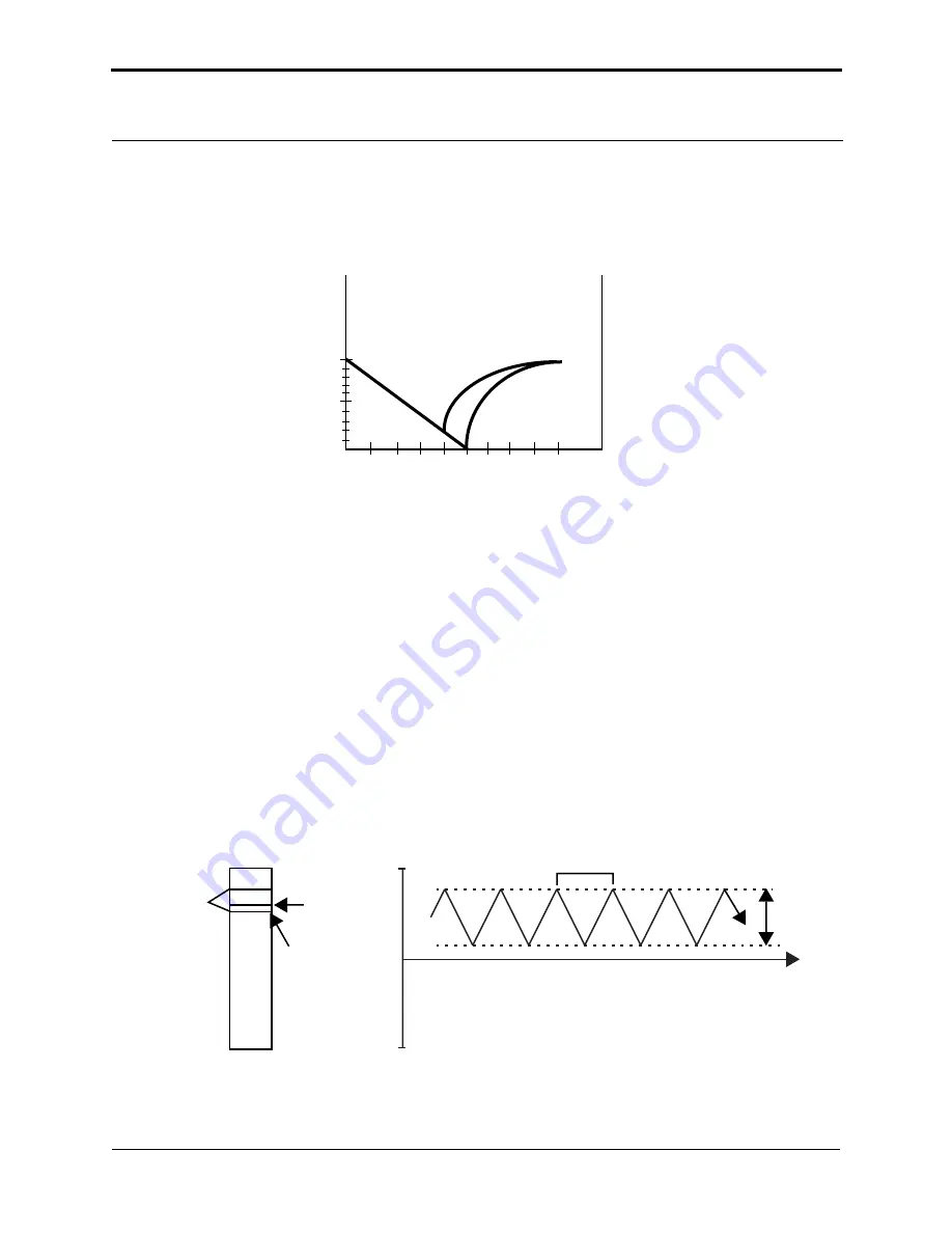
First, magnet #1 is weaker, attaching to the steel plate with 7N of pulling force at 6cm, and magnet
#2 is stronger, attaching at 7cm with 10N.
Figure 11.1b
Pulling Forces Graph
This oversimpli
fi
ed model depicts activity between SPM tips and various materials. In reality, SPM
force plots reveal far more. For example, by combining force curves at regularly spaced intervals
across the sample, you may generate a force map of the sample’s electric properties, elastic
modulus, and chemical bonding strengths.
11.2 Force Calibration Mode
The
Force Calibration
command in the
View
>
Force Mode
>
Calibrate
menu allows you to
quickly check the interaction between cantilever and sample. In
Force Calibration
mode, the X
and Y voltages applied to the piezo tube are held constant while a triangular waveform (similar to
the one depicted below) is applied to the Z piezo tube.
Figure 11.2a
Z-axis Voltage During Force Plot Scanning
Height above steel plate (cm)
0
-10
10
Magnet #1
Magnet #2
+1
0
-1
-5
N
kg
2
3
4
5
6
7
8
9 10 11
Time
Z scan start
- 220
+ 220
Scan size
Scan period (sec)
1
Z scan rate (Hz)
-------------------------------------------
=
Scan period
Z V
oltage
Retracted
Extended
Ramp Size
Z Scan Start
Z Center


