background image

Goodrive10 inverters                                                                                                            Communication protocol                                                                                   

89 

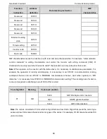
Function 

instruction 

Address 

definition   

Data meaning instruction 

R/W 

characteristics 

Reserved 

300FH 


Reserved 

3010H 


Reserved 

3011H 


Reserved 

3012H 


Reserved 

3013H 


External counting 

value   

3014H 


Torque setting   

3015H 


Inverter code   

3016H 


Fault code   

5000H 


R/W characteristics means the function is with read and write characteristics. For example, “communication 

control  command”  is  writing  chrematistics  and  control  the  inverter  with  writing  command  (06H).  R 

characteristic can only read other than write and W characteristic can only write other than read.   

Note: 

When operate on the inverter  with  the table above, it is  necessary to enable some  parameters. For 

example,  the  operation  of  running  and  stopping,  it  is  necessary  to  set  P00.01  to  communication  running 

command  channel  and  set  P00.02  to  MODBUS  communication  channel.  And  when  operate  on  “PID 

reference

”, it is necessary to set P09.00 to


“MODBUS communication setting”.

The encoding rules for device 

codes (corresponds to identifying code 2103H of the inverter) 
 

Code high 8bit   

Meaning   

Code low 8 position 

Meaning 

01 

GD 

0x0b 

GD100 simple vector inverters 

0x0c 

GD200 general inverters   

0x0d 

GD10 mini inverters 


Note: 

the code is consisted of 16 bit which is high 8 bits and low 8 bits. High 8 bits mean the motor type 

series and low 8 bits mean the derived motor types of the series. For example, 0110H means Goodrive100 

vector inverters. 


Summary of Contents for Goodrive 10

Page 1: ......

Page 2: ...3 Installation Guidelines 13 3 1 Mechanical installation 13 3 2 Standard wiring 16 3 3 Layout protection 19 4 Keypad Operation Procedure 20 4 1 Keypad displaying 22 4 2 Keypad operation 24 5 Function...

Page 3: ...r chart 98 Appendix C Peripherial options and parts 100 C 1 Peripherial wiring 100 C 2 Power supply 101 C 3 Cables 101 C 4 Breaker and electromagnetic contactor 102 C 5 Reactors 103 C 6 Filter 104 C 7...

Page 4: ...ns People working on the device should take part in professional electrical and safety training receive the certification and be familiar with all steps and requirements of installing commissioning op...

Page 5: ...combustible materials Connect the braking optional parts braking resistors or feedback units according to the wiring diagram Don t operate on the inverter if there is any damage or components loss to...

Page 6: ...be provided Note Do not switch on off the input power supply of the inverter frequently For inverters that have been stored for a long time check and fix the capacitance and try to run it again befor...

Page 7: ...Goodrive10 inverters Safety precautions 6 1 3 4 What to do after scrapping There are heavy metals in the inverter Deal with it as industrial effluent...

Page 8: ...type to verify that there is no overload of the inverter during work and check that whether the drive needs to modify the power degree 2 Check that the actual current of the motor is less than the rat...

Page 9: ...and power cables are run separately and the routation complies with EMC requirement 5 Check that all grounding systems are properly grounded according to the requirements of the inverter 6 Check that...

Page 10: ...rated current 1 minute 180 of rated current 10 seconds 200 of rated current 1 second Running control Key functions Stop mode and anti overtemperature of the bus Temperature measurement accuracy Overt...

Page 11: ...kW three phase 380V 0 75 2 2kW Braking unit Embedded DC reactor Not optional Braking resistor Optional and external EMC filter C2 filter 2 3 Name plate Fig 2 1 Name plate 2 4 Type designation key The...

Page 12: ...braking unit 2 5 Rated specifications Model Output power kW Input current A Output current A Single phase 220V GD10 0R2G S2 B 0 2 4 9 1 6 GD10 0R4G S2 B 0 4 6 5 2 5 GD10 0R7G S2 B 0 75 9 3 4 2 GD10 1R...

Page 13: ...ts and components 3 POWER indicator POWER indicator 4 Side cover Protect the internal components 5 Simple name plate See Type Designation Key for detailed information 6 Keypad port Connect the keypad...

Page 14: ...ured maintenance range may occur 3 1 Mechanical installation 3 1 1 Installation environment The installation environment is the safeguard for a full performance and long term stable functions of the i...

Page 15: ...erials such as wood keep away from direct sunlight oil mist steam and vibration environment Altitude Below 1000m If is installed above 1000m of the sea level derate 1 for every additional 100m Vibrati...

Page 16: ...1 Installation manner 1 Mark the hole location The location of the holes is shown in the dimension drawings in the appendix 2 Fix the screws or bolts to the marked locations 3 Position the drive onto...

Page 17: ...ng the braking resistor cable remove the yellow labels of PB and from the terminal blocks Otherwise poor connection may occur 3 2 2 Terminals figure of main circuit R L S N T PB U V W Fig 3 4 Terminal...

Page 18: ...3 2 3 Wiring of terminals in main circuit 1 Fasten the grounding conductor of the input power cable with the grounding terminal of the inverter PE by 360 degree grounding technique Connect the phase c...

Page 19: ...V reference zero potential AO 1 Output range 0 10V or 0 20mA 2 The voltage or the current output is depended on J2 3 Deviation 1 25 S1 Switch input 1 1 Internal impedance 3 3k 2 0 4V corresponds to lo...

Page 20: ...inverter is connected to multiple motors a separate thermal overload switch or a circuit breaker must be used for protecting each cable and motor These devices may require a separate fuse to cut off...

Page 21: ...rter is in the stopping state LED blinking means the inverter is in the parameter autotune state LED on means the inverter is in the running state FWD REV FED REV LED LED off means the inverter is in...

Page 22: ...RPM speed unit A Current unit Percentage V Voltage unit 3 Code display ing zone 5 figure LED display displays various monitoring data and alarm code such as set frequency and output frequency Display...

Page 23: ...ate of Goodrive10 series inverters is divided into stopping state parameter running state parameter function code parameter editing state and fault alarm state and so on 4 1 1 Displayed state of stopp...

Page 24: ...7 06 can select the parameter to be displayed or not by bit and SHIFT can shift the parameters form left to right QUICK JOG P07 02 2 can shift the parameters from right to left 4 1 3 Displayed state o...

Page 25: ...r the third level menu if the parameter has no flickering bit it means the function code cannot be modified The possible reasons could be 1 This function code is not modifiable parameter such as actua...

Page 26: ...ot enter it Fig 4 4 Sketch map of password setting 4 2 3 How to watch the inverter state through function codes Goodrive10 series inverters provide group P17 as the state inspection group Users can en...

Page 27: ...nal factory set value of the function parameter The fifth column Modify the modifying character of function codes the parameters can be modified or not and the modifying conditions below is the instru...

Page 28: ...Upper limit of the running frequency The upper limit of the running frequency is the upper limit of the output frequency of the inverter which is lower than or equal to the maximum frequency Setting...

Page 29: ...00 06 or P00 07 equals to 6 7 PID control setting The running mode of the inverter is process PID control when P00 06 7 or P00 07 7 It is necessary to set P09 The running frequency of the inverter is...

Page 30: ...me which can be selected by P05 The factory default ACC DEC time of the inverter is the first group Setting range of P00 11 and P00 12 0 0 3600 0s Depend on model P00 12 DEC time 1 Depend on model P00...

Page 31: ...frequency At the same time the leakage and electrical magnetic interference will increase Applying low carrier frequency is contrary to the above too low carrier frequency will cause unstable running...

Page 32: ...ation may occur to the low inertia load during starting 0 P01 01 Starting frequency of direct start up Starting frequency of direct start up means the original frequency during the inverter starting S...

Page 33: ...utput frequency during the set time When the frequency decreases to 0 the inverter stops 1 Coast to stop after the stop command becomes valid the inverter ceases the output immediately And the load co...

Page 34: ...range 0 0 3600 0s 0 00s P01 14 Switching between FWD REV rotation Set the threshold point of the inverter 0 Switch after 0 frequency 1 Switch after the starting frequency 2 Switch after a delay time...

Page 35: ...it one if the set frequency is above the lower limit one again and it lasts for the time set by P01 20 the inverter will come back to the running state automatically 0 P01 20 Hibernation restore delay...

Page 36: ...a stand by state and wait for the delay time set by P01 23 Setting range 0 0 60 0s 0 0s P01 24 Delay of the stopping speed Setting range 0 0 100 0 s 0 0s P02 Group Motor 1 P02 01 Asynchronous motor ra...

Page 37: ...the common motors will be weakened the corresponding electric heat protection will be adjusted properly The low speed compensation characteristic mentioned here means reducing the threshold of the ove...

Page 38: ...boost Torque boost to the output voltage for the features of low frequency torque P04 01 is for the Max Output voltage Vb P04 02 defines the percentage of closing frequency of manual torque to fb Torq...

Page 39: ...The setting range of P04 03 0 00Hz P04 05 The setting range of P04 04 P04 06 and P04 08 0 0 110 0 The setting range of P04 05 P04 03 P04 07 The setting range of P04 07 P04 05 P02 02 the rated frequenc...

Page 40: ...may occur These phenomena can be canceled by adjusting this parameter The setting range of P04 10 0 100 The setting range of P04 11 0 100 The setting range of P04 12 0 00Hz P00 03 the Max frequency 1...

Page 41: ...nter reset 30 ACC DEC prohibition 31 Counter trigger 33 Cancel the frequency change setting temporarily 34 DC brake 36 Shift the command to the keypad 37 Shift the command to the terminals 38 Shift th...

Page 42: ...REV Sin is natural closed 3 3 wire control 2 Sin is the enabling terminal on this mode if set Si i 1 5 to 3 when K is switched on the control of FWD and REV is valid when K is switched off the control...

Page 43: ...limit of AI1 The function code defines the relationship between the analog input voltage and its corresponding set value If the analog input voltage beyond the set minimum or maximum input value the i...

Page 44: ...ange of P05 35 100 0 100 0 The setting range of P05 36 0 000s 10 000s The setting range of P05 37 0 00V P05 39 The setting range of P05 38 100 0 100 0 The setting range of P05 39 P05 37 10 00V The set...

Page 45: ...minals The function code is used to set the pole of the output terminal When the current bit is set to 0 input terminal is positive When the current bit is set to 1 input terminal is negative BIT3 BIT...

Page 46: ...and analog output When the output value exceeds the range of set maximum or minimum output it will count according to the low limit or upper limit output When the analog output is current output 1mA...

Page 47: ...toring to the default value can clear the password please use it with caution P07 02 QUICK JOG function 0 No function 1 Jogging running Press QUICK JOG to realizes the jogging running 2 Shift the disp...

Page 48: ...th valid for panel and communication control 3 Valid for all control modes 0 P07 05 The parameter selection1 of running state 0x0000 0xFFFF BIT0 running frequency Hz on BIT1 set frequency Hz flickerin...

Page 49: ...analog AI2 value V on BIT11 current stage in multi stage speed BIT12 pulse counters 0x00FF P07 08 Frequency display coefficient 0 01 10 00 Displayed frequency running frequency P07 08 1 00 P07 09 Rot...

Page 50: ...FFF P07 23 Factory bar code 3 0x0000 0xFFFF P07 24 Factory bar code 4 0x0000 0xFFFF P07 25 Factory bar code 5 0x0000 0xFFFF P07 26 Factory bar code 6 0x0000 0xFFFF P07 27 Current fault type 0 No fault...

Page 51: ...val END 25 Electrical overload OL3 36 Undervoltage fault LL P07 33 Current fault running frequency 0 00Hz P07 34 Ramp reference frequency at current fault 0 00Hz P07 35 Output voltage at current fault...

Page 52: ...ault 0V P07 44 The output current at the previous fault 0 0A P07 45 Bus voltage at the previous fault 0 0V P07 46 The Max temperature at the previous fault 0 0 P07 47 Input terminals state at the prev...

Page 53: ...efer to P00 11 and P00 12 for detailed definition Goodrive100 series define four groups of ACC DEC time which can be selected by P5 group The first group of ACC DEC time is the factory default one Set...

Page 54: ...verse range The traverse running is limited by upper and low frequency The traverse range relative to the center frequency traverse range AW center frequency traverse range P08 15 Sudden jumping frequ...

Page 55: ...26 0 P08 25 0 P08 26 Reference counting value 0 P08 27 Setting running time Pre set running time of the inverter When the accumulative running time achieves the set time the multi function digital ou...

Page 56: ...he below or above range of the set frequency the multi function digital output terminal will output the signal of frequency arrival see the diagram below for detailed information The setting range 0 0...

Page 57: ...frequency exceeds 2k at low speed limit to 2k 2 No limt for the carrier frequency at low speed 0x01 P08 41 Over commission selection 0 Invalid 1 Valid 1 P08 42 Keypad data control setting 0x000 0x122...

Page 58: ...UP terminal frequency increasing integral ratio 0 01 50 00 Hz s 0 50 Hz s P08 46 DOWN terminal frequency integral ratio 0 01 50 00 Hz s 0 50 Hz s P08 47 Action when the frequency setting is off 0x000...

Page 59: ...When the frequency command selection P00 06 P00 07 is 7 the running mode of the inverter is procedure PID control The parameter determines the target reference channel during the PID procures 0 Keypad...

Page 60: ...00 1 00 P09 05 Interval time Ti This parameter determines the speed of PID adjustor to carry out integral adjustment on the deviation of PID feedback and reference When the deviation of PID feedback...

Page 61: ...justor output 100 0 corresponds to Max Frequency Setting range of P09 09 P09 10 100 0 Setting range of P09 10 100 0 P09 09 100 0 P09 10 Output lower limit of PID 0 0 P09 11 Feedback offline detection...

Page 62: ...me with the setting direction if the output of PID adjustment is different from the current running direction the internal will output 0 forcedly 1 Opposite to the setting direction P10 Group Simple P...

Page 63: ...6 the relationship between S1 S2 S3 S4 terminals and multi stage speed is as following S1 OFF ON OFF ON OFF ON OFF ON S2 OFF OFF ON ON OFF OFF ON ON S3 OFF OFF OFF OFF ON ON ON ON S4 OFF OFF OFF OFF O...

Page 64: ...ency at P11 02 to make the inverter generate power again The returning power can maintain the bus voltage to ensure a rated running of the inverter until the recovery of power Voltage degree 220V 380V...

Page 65: ...ing If it exceeds the level continuously the output frequency will keep on decreasing to the lower limit If the output current is detected to be lower than the limit level the inverter will accelerate...

Page 66: ...erter stops when overloading or underloading LED hundreds 0 Detection all the time 1 Detection in constant running Setting range of P11 09 P11 11 200 Setting range of P11 10 0 1 60 0s P11 11 Detection...

Page 67: ...Note The address of the slave cannot set to 0 1 P14 01 Baud rate Set the digital transmission speed between the upper monitor and the inverter 0 1200BPS 1 2400BPS 2 4800BPS 3 9600BPS 4 19200BPS 5 384...

Page 68: ...nication overtime the system will report 485 communication faults CE Generally set it as invalid set the parameter in the continuous communication to monitor the communication state 0 0s P14 05 Transm...

Page 69: ...The rotation speed of the motor Display the rotation speed of the motor Range 0 65535RPM 0 RPM P17 08 Motor power Display current power of the motor Setting range 300 0 300 0 the rated current of the...

Page 70: ...Display analog AI2 input signal Range 10 00 10 00V 0 00V P17 22 HDI input frequency Display HDI input frequency Range 0 00 50 00kHz 0 00 kHz P17 23 PID reference value Display PID reference value Ran...

Page 71: ...instruction of parameters Default value Modify P17 36 Output torque Display the output torque Positive value is in the electromotion state and negative is in the power generating state Range 3000 0Nm...

Page 72: ...control circuit are normal Measurement by millimeter Conforming to the manual Keypad Ensure the display is clear enough Visual examination The characters are displayed normally Ensure the characters...

Page 73: ...ors Ensure whether there is replacement and splitting caused by overheating Smelling and visual examination NA Ensure that there is no offline Visual examination or remove one ending to coagulate or m...

Page 74: ...25 000 operating hours The actual life span depends on the inverter usage and ambient temperature The operating hours can be found through P07 14 accumulative hours of the inverter Fan failure can be...

Page 75: ...verter Add 25 rated voltage for 2 hours Add 50 rated voltage for 2 hours Add 75 rated voltage for 2 hours Add 100 rated voltage for 2 hours The method of using power surge to charge for the inverter T...

Page 76: ...nverter can be reset by pressing the keypad key STOP RST through digital input or by switching the power light When the fault has been removed the motor can be restarted 6 2 3 Fault instruction and so...

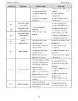
Page 77: ...oltage of the power supply is too low Check the input power of the supply line OL1 Motor overload 1 The voltage of the power supply is too low 2 The motor setting rated current is incorrect 3 The moto...

Page 78: ...ng 4 There is strong interference to the communication 1 Set proper baud rate 2 Check the communication connection distribution 3 Set proper communication address 4 Chang or replace the connection dis...

Page 79: ...f singles impact Generally the user can set PC PLC IPC and HMI as the masters to realize central control Setting certain device as the master is a promise other than setting by a bottom or a switch or...

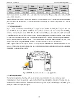
Page 80: ...to the 485 terminal It is recommended to use the shield twisted pairs When applying RS232 RS485 converter if the RS232 interface of the computer is connected to the RS232 interface of the converter th...

Page 81: ...the controller is set to communicate by RTU mode in Modbus network every 8bit byte in the message includes two 4Bit hex characters Compared with ACSII mode this mode can send more data at the same ba...

Page 82: ...TART T1 T2 T3 T4 transmission time of 3 5 bytes ADDR Communication address 0 247 decimal system 0 is the broadcast address CMD 03H read slave parameters 06H write slave parameters DATA N 1 DATA 0 The...

Page 83: ...is based on the CRC calculation method The CRC field is two bytes including 16 figure binary values It is added into the frame after calculated by transmitting device The receiving device recalculate...

Page 84: ...0H Low bit of the start bit 04H High bit of data number 00H Low bit of data number 02H CRC low bit 85H CRC high bit CAH END T1 T2 T3 T4 transmission time of 3 5 bytes T1 T2 T3 T4 between START and END...

Page 85: ...ith the fact that the high bit is in the front and the low bit is in the behind of the message the data of data address 0004H is 1388H and the data of data address 0005H is 0000H CRC occupies 2 bytes...

Page 86: ...nosis Meaning of sub function codes Sub function Code Description 0000 Return to inquire information data For example The inquiry information string is same as the response information string when the...

Page 87: ...hen the low bit of the parameter is 05 then t he function code address is 0505H and the parameter address of P10 01 is 0A01H Note PE group is the factory parameter which can not be read or changed Som...

Page 88: ...ing value 2001H Communication setting frequency 0 Fmax unit 0 01Hz W R 2002H PID reference range 0 1000 1000 corresponds to100 0 2003H PID feedback range 0 1000 1000 corresponds to100 0 W R 200AH Virt...

Page 89: ...trol 01 terminal control 10 communication control Fault code of the inverter 2102H See the fault type instruction R Identifying code of the inverter 2103H Goodrive10 0x010d R Setting frequency 3001H C...

Page 90: ...te on the inverter with the table above it is necessary to enable some parameters For example the operation of running and stopping it is necessary to set P00 01 to communication running command chann...

Page 91: ...ata received by the upper monitor is 50 then the hibernation restore delay time is 5 0 5 0 50 10 If Modbus communication is used to control the hibernation restore delay time as 5 0s Firstly 5 0 can b...

Page 92: ...Written not allowed It only happen in write command the reason maybe 1 The written data exceeds the parameter range 2 The parameter should not be modified now 3 The terminal has already been used 08H...

Page 93: ...table above its name is operation failed and its meaning is that the parameter setting in parameter writing is invalid For example the function input terminal can not be set repeatedly 7 4 7 Example o...

Page 94: ...writing command 06H Make the inverter with the address of 03H to run forward See table 1 the address of communication control command is 2000H and forward running is 0001 See the table below The comma...

Page 95: ...imed by 100 is 10000 and the corresponding hex is 2710H The command sent by the master If the operation is successful the response may be as below the same with the command sent by the master Note the...

Page 96: ...on protects the input bridge of the drive against overload 2 The ratings apply at ambient temperature of 40 C 3 It is important to check that in Common DC systems the power flowing through the common...

Page 97: ...s establishments connected to a low voltage network which supplies buildings used for domestic purposes Second environment includes establishments connected to a network not directly supplying domesti...

Page 98: ...tigation measures may be required A 3 2 Category C3 The immunity performance of the drive complies with the demands of IEC EN 61800 3 second environment The emission limits are complied with the follo...

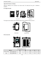
Page 99: ...tion hole 9 5 7 56 32 17 8 4 42 7 18 2 18 9 42 5 2 19 8 26 2 4 5 34 3 62 6 5 15 3 15 13 9 75 62 48 1 16 9 16 The keypad can be installed on the installation bracket Bu the installation bracket is opti...

Page 100: ...153 2 Three phase 220V GD10 0R2G 2 B 85 0 74 0 145 5 131 5 134 2 GD10 0R4G 2 B 85 0 74 0 145 5 131 5 134 2 GD10 0R7G 2 B 85 0 74 0 145 5 131 5 153 2 GD10 1R5G 2 B 100 0 89 0 170 5 154 0 153 2 GD10 2R2...

Page 101: ...tions Cables Device to transfer the electronic signals Breaker Prevent from electric shock and protect the power supply and the cables system from overcurrent when short circuits occur Please select t...

Page 102: ...k that the voltage degree of the inverter complies with the voltage of the supply power voltage C 3 Cables C 3 1 Power cables Dimension the input power and motor cables according to local regulations...

Page 103: ...ance should be no more than 100m 2 Terminals P1 PB and connects the DC reactor options and parts C 4 Breaker and electromagnetic contactor It is necessary to add fuse for the avoidance of overload It...

Page 104: ...0 C 5 Reactors High current in the input power circuit may cause damage to the rectifying components It is appropriate to use AC reactor in the input side for the avoidance of high voltage input of th...

Page 105: ...2 The power factor of the input side is above 90 after adding DC reactor 3 The rated derate voltage of the output reactor is 1 15 4 Above options are external the customer should indicate when purchas...

Page 106: ...indicate when purchasing C 6 2 C2 filters The inverter Input filter Output filter GD10 0R2G S2 B FLT PS2010H B FLT L02010H B GD10 0R4G S2 B FLT PS2010H B FLT L02010H B GD10 0R7G S2 B FLT PS2010H B FLT...

Page 107: ...Read carefully the instructions of braking resistors or units before connecting them with the inverter Do not connect the braking resistor with other terminals except for PB and Damage to the inverter...

Page 108: ...for the particular drive The drive and the internal chopper are not able to handle the overcurrent caused by the low resistance Increase the power of the braking resistor properly in the frequent bra...

Page 109: ...ce inquirie Address any inquiries about the product to Universal Motors quoting the type designation and serial number of the unit in question D 2 Document library on the Internet You can find manuals...

Page 110: ......

Reviews: