Goodrive10 inverters Appendix C
106
C.7 Braking system
C.7.1 Select the braking components
The motor will become a generator if its actual rotating speed is higher than the corresponding speed of the
reference frequency. As a result, the inertial energy of the motor and load return to the inverter to charge the
capacitors in the main DC circuit. When the voltage increases to the limit, damage may occur to the inverter.
It is necessary to apply braking resistor to avoid this accident happens.
Only qualified electricians are allowed to design, install, commission and operate on the
inverter.
Follow the instructio
ns in “warning” during working. Physical injury or death or serious
property may occur.
Only qualified electricians are allowed to wire. Damage to the inverter or braking options
and part may occur. Read carefully the instructions of braking resistors or units before
connecting them with the inverter.
Do not connect the braking resistor with other terminals except for PB and (-). Damage
to the inverter or braking circuit or fire may occur.
Connect the braking device with the inverter according to the diagram. Incorrect wiring
may cause damage to the inverter or other devices.
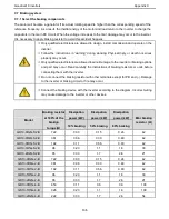
Model
Braking resistor
at 100% of the
brakign
torque(
Ω)
Dissipation
power (kW)
Dissipation
power (kW)
Dissipation
power (kW)
Mini braking
resistor
(Ω)
10% braking
50% braking
80% braking
GD10-0R2G-S2-B
722
0.03
0.15
0.24
42
GD10-0R4G-S2-B
361
0.06
0.30
0.48
42
GD10-0R7G-S2-B
192
0.11
0.56
0.90
42
GD10-1R5G-S2-B
96
0.23
1.1
1.8
30
GD10-2R2G-S2-B
65
0.33
1.7
2.6
21
GD10-0R2G-2-B
722
0.03
0.15
0.24
42
GD10-0R4G-2-B
361
0.06
0.30
0.48
42
GD10-0R7G-2-B
192
0.11
0.56
0.90
42
GD10-1R5G-2-B
96
0.23
1.1
1.8
30
GD10-2R2G-2-B
65
0.33
1.7
2.6
21
GD10-0R7G-4-B
653
0.11
0.6
0.9
100
GD10-1R5G-4-B
326
0.23
1.1
1.8
100
GD10-2R2G-4-B
222
0.33
1.7
2.6
54


