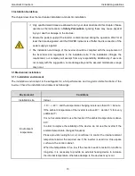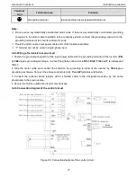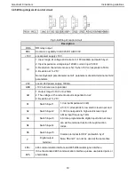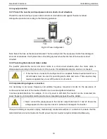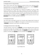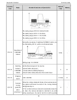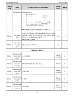
Goodrive10 inverters Keypad operation procedure
21
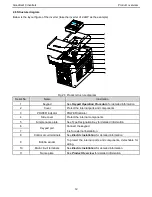
Serial
No.
Name
Description
TRIP
LED for faults
LED on when the inverter is in the fault state; LED off in
normal state; LED blinking means the inverter is in the
overload pre-alarm state.
2
Unit
LED
Mean the unit displayed currently
Hz
Frequency unit
RPM
speed unit
A
Current unit
%
Percentage
V
Voltage unit
3
Code
display
ing
zone
5-figure LED display displays various monitoring data and alarm code such as set
frequency and output frequency.
Displayed
word
Correspon
ding word
Displayed
word
Correspon
ding word
Displayed
word
Correspon
ding word
0
1
2
3
4
5
6
7
8
9
A
B
C
d
E
F
H
I
L
N
n
o
P
r
S
t
U
v
.
-
4
Digital
potenti
ometer
Corresponds to AI1.
5
Button
Progra
mming
key
Enter or escape from the first level menu and remove the
parameter quickly


