Goodrive10 inverters Function codes
61
Function
code
Name
Detailed instruction of parameters
Default
value
Modify
selection
0: Keep on integral adjustment when the frequency
achieves the upper and low limit; the integration shows the
change between the reference and the feedback unless it
reaches the internal integral limit. When the trend between
the reference and the feedback changes, it needs more
time to offset the impact of continuous working and the
integration will change with the trend.
1: Stop integral adjustment when the frequency reaches the
upper and low limit. If the integration keeps stable, and the
trend between the reference and the feedback changes,
the integration will change with the trend quickly.
LED tens:
0: The same with the setting direction; if the output of PID
adjustment is different from the current running direction,
the internal will output 0 forcedly.
1:Opposite to the setting direction
P10 Group Simple PLC and multi-stage speed control
P10.02
Multi-stage
speed 0
100.0% of the frequency setting corresponds to the Max.
Frequency P00.03.
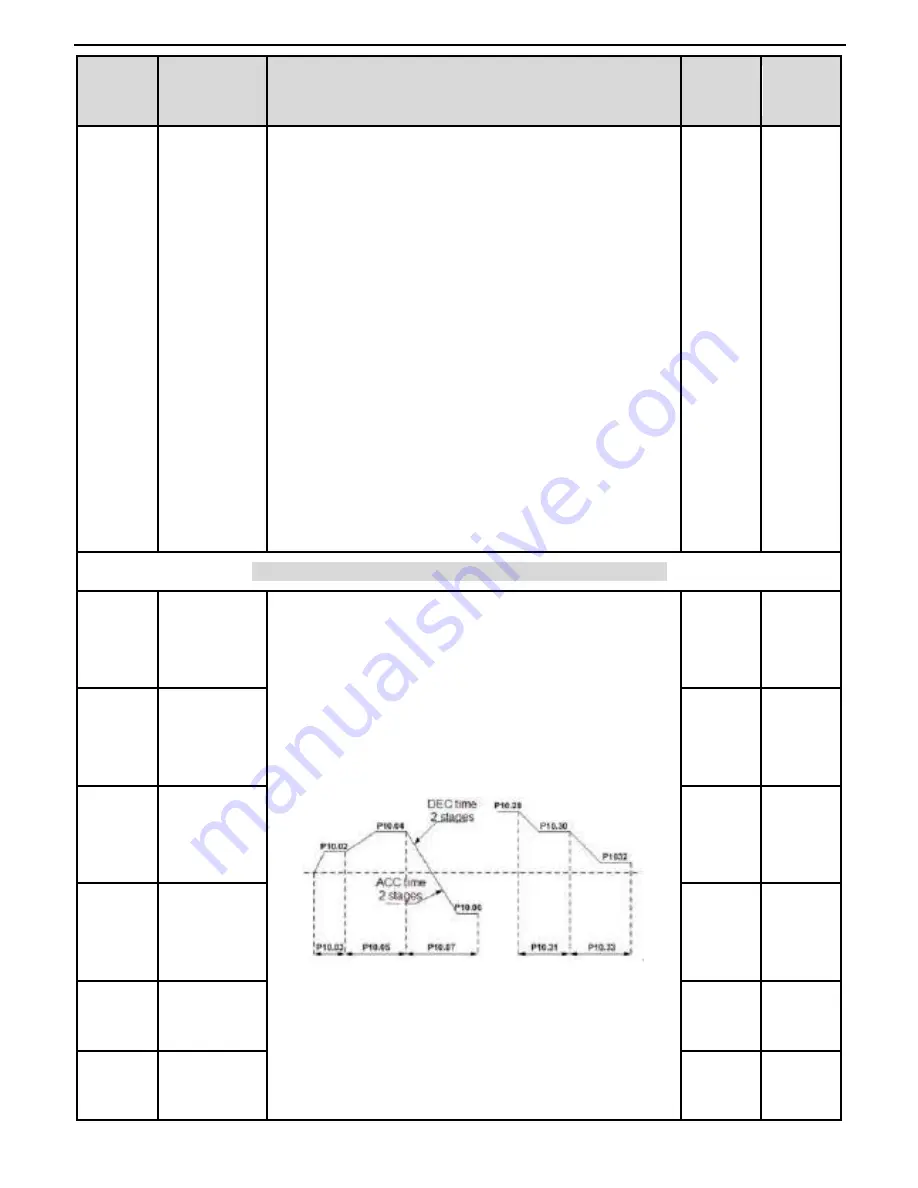
When selecting simple PLC running, set P10.02~P10.33 to
define the running frequency and direction of all stages.
Note: The symbol of multi-stage determines the running
direction of simple PLC. The negative value means reverse
rotation.
Multi-stage speeds are in the range of --f
max
~f
max
and it can
be
Goodrive10 series inverters can set 16 stages speed,
selected by the combination of multi-stage terminals 1~4,
corresponding to the speed 0 to speed 15.
0.0%
○
P10.04
Multi-stage
speed 1
0.0%
○
P10.06
Multi-stage
speed 2
0.0%
○
P10.08
Multi-stage
speed 3
0.0%
○
P10.10
Multi-stage
speed 4
0.0%
○
P10.12
Multi-stage
speed 5
0.0%
○


