Goodrive10 inverters Function codes
28
Function
code
Name
Detailed instruction of parameters
Default
value
Modify
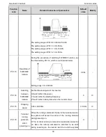
Analog input terminal sets the frequency. There are 2
standard analog input terminal, of which AI1 is adjusted
through digital potentiometer, AI2 (0~10V/0~20mA)can be
switched by the jumper.
Note: when AI2 selects 0~20mA input, 20mA corresponds
to 10V.
100.0% of the analog input corresponds to P00.03,
-100.0% of the analog input corresponds to the reverse
P00.03.
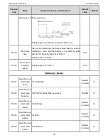
6: Multi-stage speed running setting
The inverter runs at multi-stage speed mode when
P00.06=6 or P00.07=6. Set P05 to select the current
running stage, and set P10 to select the current running
frequency.
The multi-stage speed has the priority when P00.06 or
P00.07 does not equal to 6, but the setting stage can only
be the 1~15 stage. The setting stage is 1~15 if P00.06 or
P00.07 equals to 6.
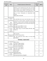
7: PID control setting
The running mode of the inverter is process PID control
when P00.06=7 or P00.07=7. It is necessary to set P09.
The running frequency of the inverter is the value after PID
effect. See P09 for the detailed information of the preset
source, preset value, feedback source of PID.
8:MODBUS communication setting
The frequency is set by MODBUS communication. See P14
for detailed information.
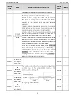
P00.08
B frequency
command
reference
0: Maximum output frequency, 100% of B frequency
setting corresponds to the maximum output frequency
1: A frequency command, 100% of B frequency setting
corresponds to the maximum output frequency. Select this
setting if it needs to adjust on the base of A frequency
command
0
○
P00.09
Combination
type of the
setting source
0: A, the current frequency setting is A freauency command
1: B, the current frequency setting is B frequency command
2: A+B, the current frequency setting is A frequency
c B frequency command
3: A-B, the current frequency setting is A frequency
0
○


