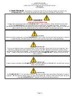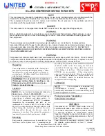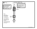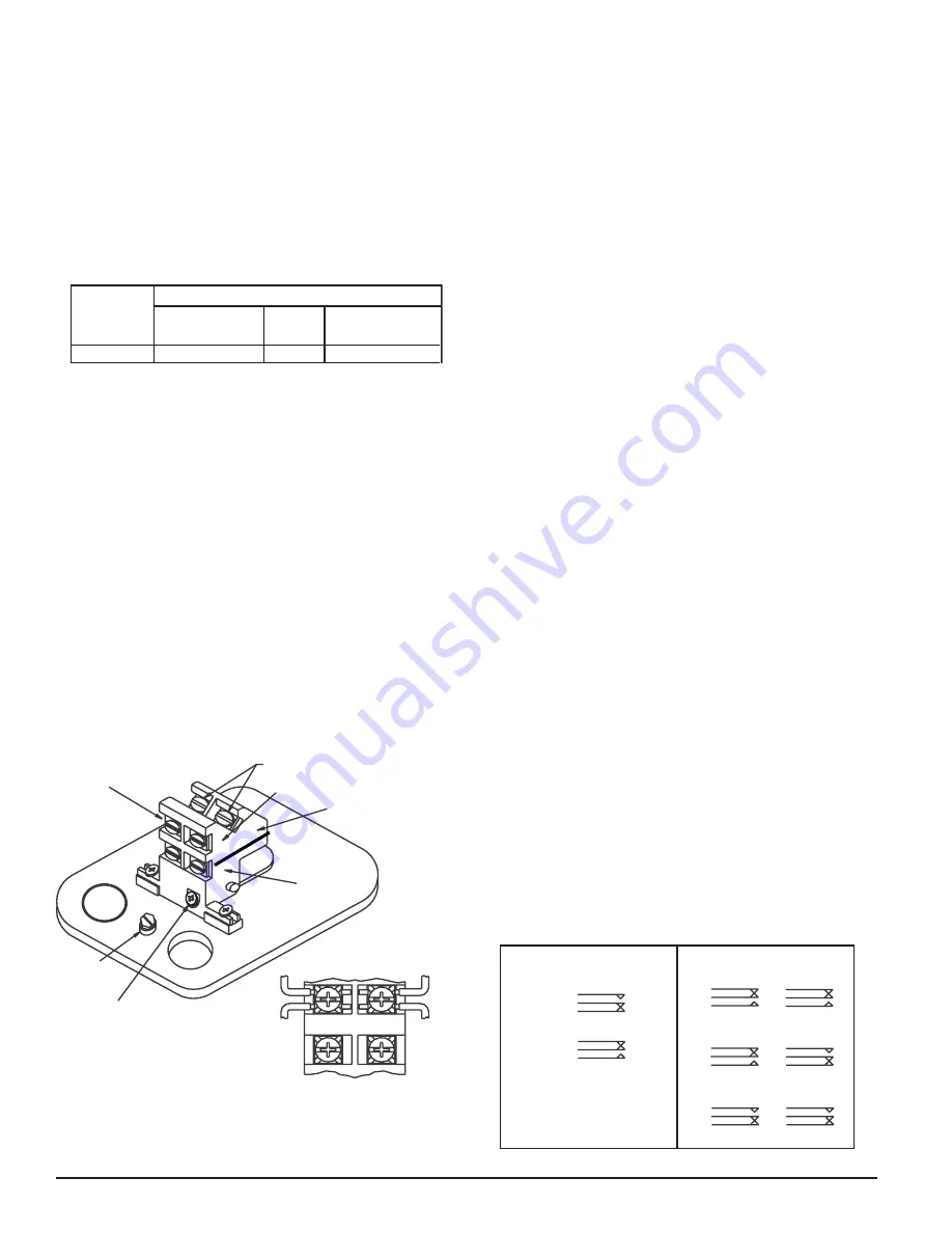
GROUND
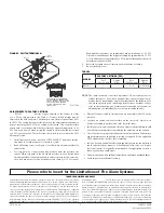
SCREW
CO
M
B
A
COMMON
TERMINALS
BREAK WIRE AS SHOWN FOR
SUPERVISION OF CONNECTION.
DO NOT ALLOW STRIPPED WIRE
LEADS TO EXTEND BEYOND
SWITCH HOUSING. DO NOT
LOOP WIRES.
SWITCH #1
SWITCH #2
SW
ITC
H #
2
LOCKING
SCREW
TERMINAL “A”
TERMINAL “B”
D770-17-00
2 I56-0986-008R
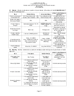
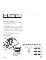
TABLE 2.
FACTORY SETTINGS (PSI)
MODEL
Fall SW2
(Low Switch)
Rise SW1
(Hi Switch)
Nominal
EPS40-1
EPS40-2
EPS120-1
EPS120-2
30
±
1.5
30
±
1.5
––
115
101.5 - 112.5
101.5 - 112.5
117.5 - 128.5
115
––
40
50
±
2.5
40
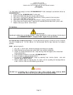
SINGLE-SWITCH MODEL — EPS40-1 AND EPS120-1
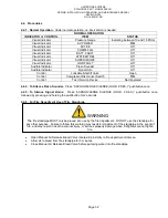
1. Install pressure switch as stated in “INSTALLATION” portion of instruc-
tion manual. Attach pressure test source to system.
2. Back off locking screw (see Fig. 4) to allow main adjustment wheel to
rotate freely.
3. Test the switch for the set point by introducing 40 PSI pressure from the
pressure test source for the EPS40-1 (115 PSI for the EPS120-1). Decrease
pressure slowly until the switch trips. Rotate main adjustment wheel,
Figure 5, (counterclockwise to increase pressure) and retest by first intro-
ducing a higher pressure than desired and slowly reducing pressure until
the switch trips. Repeat process until switch trip point is at desired pres-
sure setting. Each number represents an approximate trip point change
of 1.8 PSI for the EPS40-1 and 6.6 PSI for the EPS120-1. For each
1
/
2
rotation of the adjustment wheel, the trip point setting changes by ap-
proximately 11 PSI for the EPS40-1 and 40 PSI for the EPS120-1.
4. Retest the set point several times to ensure accuracy of setting.
5. Re-seat locking screw.
C0141-01
FIGURE 3. TYPICAL PIPING DIAGRAM FOR EPS120-1, EPS120-2
FIGURE 2. TYPICAL PIPING DIAGRAM FOR EPS40-1, EPS40-2
DRY
PIPE
VALVE
OS & Y
VALVE
WATER
BY-PASS
TEST
VALVE
LOCAL ALARM
SHUT OFF
VALVE
WATER
MOTOR
GONG
CHECK
VALVE
EPS40
CHECK
VALVE
AIR LINE
SHUT-OFF
VALVE
INSTALL
BLEEDER
VALVE FOR
TESTING
EPS10
DRY SYSTEM
WIRE TO SUPERVISORY
CIRCUIT OF FIRE ALARM
CONTROL PANEL
WIRE TO ALARM
INDICATING CIRCUIT
OF FIRE ALARM
CONTROL PANEL
TO
SPRINKLER
SYSTEM
FIGURE 4. SWITCH LOCATION:
W0185-01
W0186-00
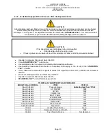
TABLE 1. ELECTRICAL CONNECTIONS (REFERENCED AT FACTORY
SETTINGS):
MODELS EPS40-1, EPS120-1
SWITCH AT NORMAL SYSTEM PRESSURE
SWITCH AT TRIP POINT
B
COM
A
A
COM
B
SWITCH 1
SW2
SW1
SWITCHES AT NORMAL SYSTEM PRESSURE
SWITCHES AT LOW TRIP POINT
SW1
SW2
MODELS EPS40-2, EPS120-2
SWITCHES AT HIGH TRIP POINT
SW1
SW2
B
COM
A
B
COM
A
B
COM
A
A
COM
B
A
COM
B
A
COM
B
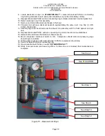
DUAL-SWITCH MODEL — EPS40-2 AND EPS120-2
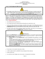
1. Install pressure switch as stated in “INSTALLATION” portion of instruc-
tion manual. Attach pressure test source to system.
2. Back out the locking screw (see Fig. 4) to allow main adjustment wheel
to turn freely.
3.
Option 1: Adjust nominal pressure setting without affecting PSI window.
a) Adjust main adjustment wheel (see Fig. 5) to desired setting using
pressure source (i.e., valve or air maintenance device).
b) Turn main adjustment wheel counterclockwise to increase (see arrow
on mounting base) or clockwise to decrease pressure. Each number
on main adjust wheel represents an approximate window shift of 1.8
psi for EPS40-2 and 6.6 psi for EPS120-2. For each
1
/
2
rotation of the
adjustment wheel the window changes by approximately 11 psi for
EPS40-2 and 40 psi for EPS120-2.
c) Retest the set point several times to ensure the accuracy of the setting.
Option 2: Adjust pressure window size and nominal setting of pres-
sure window.
a) Adjust main adjustment wheel (see Fig. 5) until high switch (SW1)
trips at desired pressure using pressure test source (valve or air main-
tenance device).
b) Refer to step B from Option 1.
c) Decrease pressure until the low switch trips (SW2).
d) Adjust
1
/
4
˝ low pressure hex head nut (see Fig. 5) to either increase
(counterclockwise) or decrease (clockwise) the window size (the low
switch will be affected).
e) The approximate sensitivity of the hex screw adjustment:
1
/
2
turn
=5
psi. A maximum of 30 psi is attainable.
4. Retest the set points several times to ensure the accuracy of the settings,
and adjust as necessary.
5. Re-seat locking screw.
NOTE: EPS40 models are able to be set to a range within 8-100psi only when
used with Victaulic series 768 and 769 FireLock NXT valves pre-set for use
with low pressure actuators. When used on Victaulic series 768 and 769
FireLock NXT all units must be 100% tested to verify pressure setting. Both
the main adjustment wheel and low pressure adjusting screw (See Figure 5)
need to be customer set and tested to insure proper functionality. For pres-
sure setting instructions refer to Installation section for dual switch models in
this manual.
WET
SYSTEM
ALARM
CHECK
VALVE
OS & Y
VALVE
OS & Y
VALVE
WATER
BY-PASS
VALVE
AIR
PRESSURE
SUPPLY
BLEEDER
TEST
VALVE
EPS120
LOCAL ALARM
SHUT OFF
VALVE
RETARD
WATER
MOTOR
GONG
C0142-01

