


UNITED FIRE SYSTEMS
STANDPIPE-
PAC™ MODEL SSS-101
DESIGN, INSTALLATION, OPERATION, AND MAINTENANCE MANUAL
REVISION 2.00
P/N 10-540101-001
Page 29
4. OPERATION
4.1 Indicators.
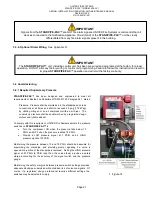
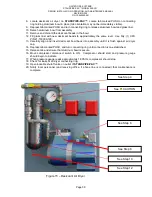
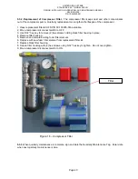
4.1.1. Pressure Gauge.
The pressure gauge indicates the approximate pressure produced by the air
compressor within the
STANDPIPE-PAC
™
piping and the standpipe.
4.1.2. Signal Horn.
The signal horn is the required audible indicator to annunciate an alarm condition. The
signal horn will sound when the pressure in the standpipe drops below approximately 7 PSIG, indicating an
impairment of the standpipe requiring correction.
4.1.3. Indicators Within Control Unit.
4.1.3.1. Visual Indicator
– “AC POWER”.
This is a green LED, visible with unit door closed or open, indicating
that AC power has been applied to the unit.
4.1.3.2. Visual Indicator
– “ACTIVE”.
This is a red LED, visible with unit door closed or open, indicating that
either the low-limit or high-limit pressure sensing switch has activated.
4.1.3.3. Visual Indicator
– “COMM. FAIL”.
This is a yellow LED, visible with unit door closed or open,
indicating failure of communications over the telephone lines (if connected).
4.1.3.4. Visual Indicator
– “BATT. FAULT”.
This is a yellow LED, visible with unit door closed or open,
indicating trouble with the backup battery.
4.1.3.5. Visual Indicator
– “SYSTEM TRBL”.
This is a yellow LED, visible with unit door closed or open,
indicating a fault on a supervised circuit.
4.1.3.6. Visual Indicator
– “SUPERVISORY”.
This is a yellow LED that is not used with
STANDPIPE-
PAC™.
4.1.3.7. Visual Indicator
– “GND FAULT”.
This is a yellow LED, visible only with unit door open, indicating a
ground fault on an external circuit.
4.1.3.8. Audible Indicator
– Piezo Sounder.
This is an audible indicator that sounds whenever an ACTIVE or
SYSTEM TRBL signal exists.
4.2.
Controls.
4.2.1. Lockable Shutoff Valve.
This valve is used during testing and maintenance to isolate the
STANDPIPE-
PAC™
from the standpipe. The normal position of this valve is OPEN. A lock should be placed on this valve to
ensure it stays in the OPEN position, and is not closed inadvertently.
4.2.2. Compressor Disconnect Switch.
This switch is used to remove power from the compressor during
testing and maintenance. The normal position of this switch is ON.
4.2.3. Test / Service Device.
This device is used ONLY during testing and maintenance. DO NOT operate this
device unless testing and maintenance procedures are being followed.
IMPORTANT
Pressure values indicated by the
STANDPIPE-
PAC™
pressure gauge are APPROXIMATE. Variation from
nominal values can be expected.