background image

Setup

15

Document Number 206465-0001

                                                                               User Guide

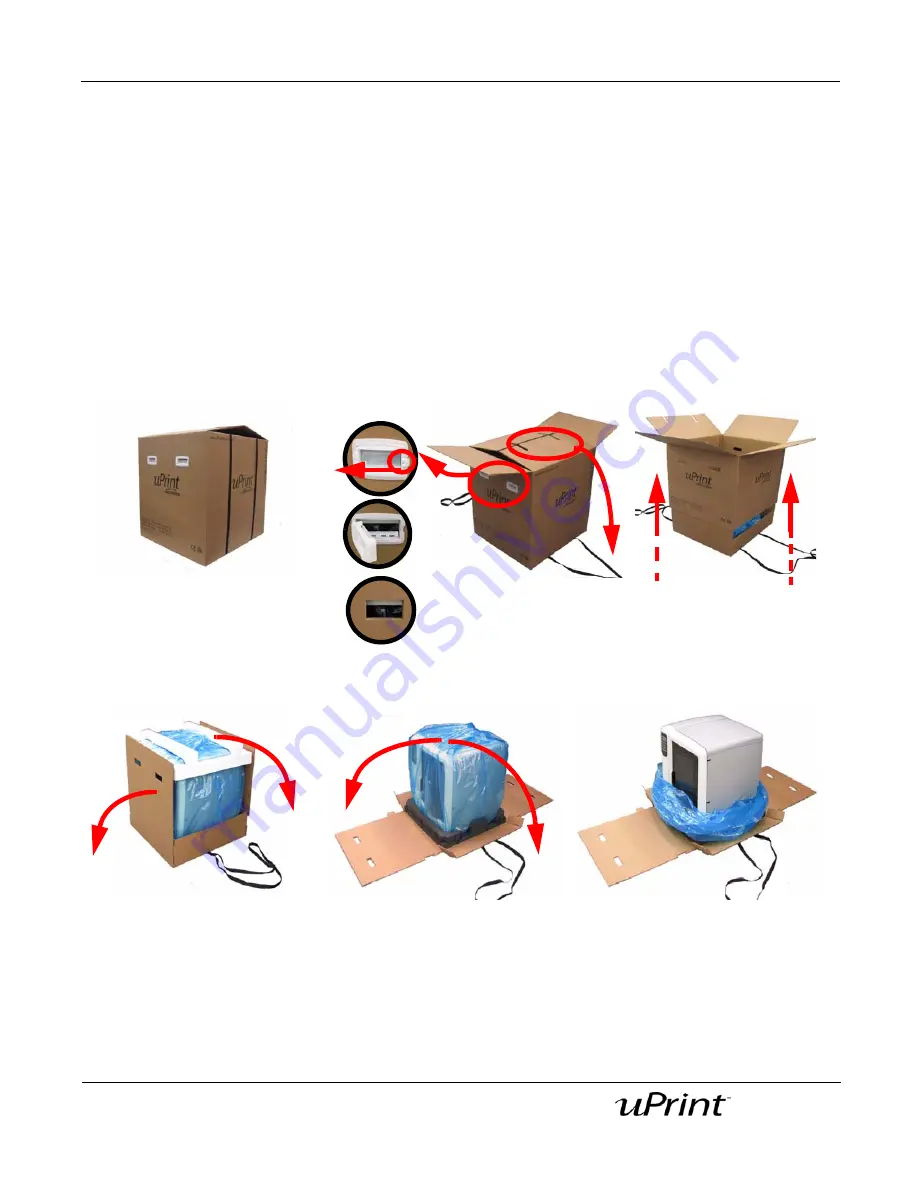
Unpacking the Printer

1.  Place the printer close to the area where it will be located.

2.

Remove the handles from the box, pulling the tabs outward. 

3.

Carefully cut the top of the box open, do NOT cut the straps that contain the box.

4.

Unfold the top of the box and remove the straps.

5.

Raise the outer box up and off of the inner box.

6.

Fold down the sides of the inner box to reveal the printer.

7.

Remove the foam from the top of the printer.

8.

Cut the top of the blue plastic bag the printer is enclosed in.

9.

Lower the plastic bag, the printer should now be visible.

Figure 8: uPrint 3D Printer

1

2

3

4

5

6

A

B

C

Summary of Contents for 180-00108 uPrint

Page 1: ...User Guide...

Page 2: ...with the furnishing performance or use of this Material Copyright 2008 Stratasys Inc All rights reserved Stratasys Dimension and CatalystEX are registered trademarks of Stratasys Inc uPrint and ABSplu...

Page 3: ...rossover cable 20 Powering ON 21 Initial Language Setup 22 Setting your default language 22 Software 22 Installing CatalystEX 22 Verifying system software 23 Networking the printer 23 Establishing com...

Page 4: ...g support material 42 Emptying the purge bucket 43 Replacing material for single material bay 43 Material bay LEDs 45 Replacing material spools 46 Removing a spool of material from the carrier 46 Stor...

Page 5: ...tip shields 69 Remove Debris Buildup 69 Vacuum Build Chamber 69 Clean Door 69 500 Hour maintenance 69 Replace the tip wipe assembly 69 Replace the tip shields 69 2000 Hour maintenance 70 Tip replacem...

Page 6: ...port Technology SST your completed parts are quickly available for review and test uPrint is an innovative combination of proprietary hardware software and material technology Welcome to the new dimen...

Page 7: ...sign indicates the presence of devices with high temperatures Always use extra care and wear safety gloves when working around heated components Gloves When performing some maintenance procedures the...

Page 8: ...ady to use immediately after completion Figure 1 Front and left side view of printer 1 Extrusion Head 9 Optional Material Bay Model Side 2 Extrusion Tips 10 Optional Material Bay Support Side 3 Guide...

Page 9: ...UPS Connection 3 Material Bay 11 Material Bay Cable Connector 4 Model Material Tube 12 RJ 45 Network Connector 5 Circuit Breaker 13 Diagnostics Cable Connector 6 AC Power Cord Connector 14 Material Ba...

Page 10: ...10 Document Number 206465 0001 User Guide Figure 3 Material spools and carriers Figure 4 Modeling base Model material spool Support material spool Support material carrier Model material carrier Model...

Page 11: ...6 x 6 in Each material carrier contains 492 cc 30 cu in of usable material enough to build continuously for about 48 hours without reloading You can add an optional second material bay for extended b...

Page 12: ...115 mm 4 5 in minimum space behind unit for air circulation 153 mm 6 in minimum space around the printer for air circulation Installation location Stable flat surface capable of holding 100Kg 220 lbs...

Page 13: ...it 1 Carefully cut the top of the box open and remove the contents 2 Remove the Welcome Kit box A and open 3 Remove the model and support material spools B 4 Remove the material guide tubes B 5 Remove...

Page 14: ...r Guide Unpacking the Material Bay 1 Carefully cut the top of the box open and lay it on its side 2 Remove the material bay A 3 Remove the material bay cable B 4 Remove the model and support carriers...

Page 15: ...x open do NOT cut the straps that contain the box 4 Unfold the top of the box and remove the straps 5 Raise the outer box up and off of the inner box 6 Fold down the sides of the inner box to reveal t...

Page 16: ...m the material bay doors See Figure 9 Figure 9 Remove the shipping foam from the material bay doors 3 The material bay has 4 holes for the feet and 2 holes for the alignment pins See Figure 10 These m...

Page 17: ...lt retaining clips in place remove the belt retaining clips and recycle See Figure 11 Figure 11 Open the chamber door and remove shipping materials WARNING The lead screw and guide rods are lubricated...

Page 18: ...interfere with modeling base installation 2 Set the modeling base on the Z platform aligning the tabs on the modeling base with the slots on the metal tray See Figure 12 3 Slide the modeling base down...

Page 19: ...you are using the optional second material bay the longer material tubes are for the lower material bay and the shorter material tubes are for the upper material bay Figure 13 Material tube connection...

Page 20: ...5 Power cable connection Network Crossover connections Connecting the network cable 1 Connect the network cable blue to the network connection at the back of the printer See Figure 16 2 Connect the ne...

Page 21: ...Powering ON Figure 17 Circuit breaker and power switch 1 Turn the circuit breaker to the ON position 2 Turn the power switch to the ON position Note After powering the printer ON it may take up to 5 m...

Page 22: ...program is the system software which is factory installed on the printer Because there are occasional changes to this software you will have to verify that you have the latest version installed Insta...

Page 23: ...ication on a dynamic network If you are on a dynamic network or not sure of your network type follow these steps to allow CatalystEX to find your printer and establish communication 1 Connect a networ...

Page 24: ...cursor one place to the right Press Last Digit to move the cursor one place to the left 7 Use the three functions listed above to set your IP address 8 After setting the final digit of the Internet Pr...

Page 25: ...d with the Welcome Kit See Connecting the network cable on page 20 2 Make sure the printer is ON and determine the Unique Device Name UDN for your printer A From Idle or Ready to Build from the displa...

Page 26: ...ter allowing your PC a minute or so to adjust to the new setting your PC should connect to your printer vii If you are still unable to connect to your printer recheck your connections and settings Sys...

Page 27: ...rial Figure 18 Opening the carrier 2 Tear open the bag and discard Note how the material and material guide are held in place with clear plastic See Figure 19 Figure 19 Removing the material spool 3 C...

Page 28: ...are different The material guide tubes install on the opposite side See Figure 20 8 Close the carrier with the material guide in place Latch both buckles completely the red tab must snap in to place...

Page 29: ...tional video can be viewed at http www uPrintDimension com productinformation customerinfo 1 From the display panel press Material the display will show Add Remove Figure 22 Adding carriers to the sin...

Page 30: ...l to the head 2 When the printer has finished loading support material to the head press Done the display will show Wait for Part or Ready to Build if a part is in the queue and will also show the amo...

Page 31: ...e material bays that you want to be active or loaded to the head Select Next Model for the next model bay this will toggle between M1 and M2 or Next Support for the next support bay this will toggle b...

Page 32: ...will be placed next to the model and support material bays that are active Note It can take up to 5 minutes for the printer to load the material to the head 5 When the material has been loaded to the...

Page 33: ...uild one of your own files Once the printer has reached Idle material has been loaded and a modeling base has been installed you can build a test part with the printer 1 From the display panel press M...

Page 34: ...y panel and keypad The uPrint display panel and keypad consist of a multiple line LCD display with two buttons used for scrolling through messages and four single line displays each with one button fo...

Page 35: ...building a part you can choose to pause set the lights either ON or OFF view the print time or material remaining and set the printer to auto power down Material From this section you can load materia...

Page 36: ...Queue Printer Services tab From this section you can check the printer history set the printer time set the printer password update printer software get printer info and export configuration files wh...

Page 37: ...is oriented when it prints Orientation impacts build speed part strength surface finish and material consumption Orientation can also affect the ability of CatalystEX to repair any problems with the...

Page 38: ...is the default support setting Basic May be used for most parts Basic support uses a consistent spacing between support tool paths Sparse Minimizes the amount of support material Sparse support uses...

Page 39: ...panel press Wait for Part The display will ask Is Model Base Installed 2 Insert a modeling base See Inserting a modeling base on page 18 3 Press Yes Waiting for Part will now be on the display 4 From...

Page 40: ...ghts are automatically ON The default time out for the lights is 30 minutes You can toggle the lights ON or OFF through the display panel You can set the chamber lights on permanently however the cham...

Page 41: ...y the file name You will then be prompted to remove the part and replace the modeling base 5 Remove the part and replace the modeling base Once the chamber door has been opened and closed the display...

Page 42: ...ove the part Note Parts are easier to remove from the modeling base when still warm Removing support material uPrint uses soluble support material which is designed to dissolve in a soap and water bas...

Page 43: ...ay panel press Material The display will show Add Remove and S1 remaining and M1 remaining Asterisks will mark the currently active material bays the material bays that are currently loaded to the hea...

Page 44: ...ded to the head press Done Replacing material for dual material bays 1 From the display panel press Material The display will show Add Remove and S1 S2 remaining and M1 M2 remaining Asterisks will mar...

Page 45: ...ecting Next Model or Next Support When done selecting press Load Selected 13 The printer will now load the selected material bays and prepare the other bays for automatic loading After they are done l...

Page 46: ...al spools into material carri ers on page 27 Storing material spools If you will not be using the printer for more than 72 hours unload and store model and support material in the storage bags provide...

Page 47: ...rial in the material detents See Figure 38 Figure 38 Material guide slot and detents 9 Cut the excess material from material guide 10 Place the material retaining clips on the spool before removing th...

Page 48: ...n the material carrier or the storage bag that came with the carrier to prevent moisture absorption Auto power down You can set the printer to automatically power down when it completes a build This o...

Page 49: ...his is done while the printer is building a part the current part will not be completed Note System cooling fans and lights will continue to operate for several minutes after the switch has been turne...

Page 50: ...on page 60 No text displayed on Display Panel Cycle power see Cycling power on page 59 Cannot communicate with system through network or crossover cable Make sure network cables are connected at the...

Page 51: ...ial is coming out of the material guide Verify material pulls freely from the carrier Verify the material tubes are free of material Load Error Filament blocked Remove the carrier and verify material...

Page 52: ...ling power on page 59 wait 60 seconds before switching power on again In most cases you will be able to continue operation However if the printer continues to shut down and display the same error cont...

Page 53: ...immediately extrude material After the tip reaches operating temperature you may need to wait up to 30 seconds before extrusion will begin 5 Press Stop to stop the extrusion 6 If material steadily fl...

Page 54: ...ocedure assumes that material is loaded to the extrusion tip If material has not been loaded see Adding material carriers to single material bay on page 29 or Adding material carriers to the dual mate...

Page 55: ...aterial idler wheel out of the way on the side that is clogged Use a 7 64 and 1 8 T Handle as illustrated in Figure 44 model side shown Figure 43 Head components Press tabs in to remove air plenum Pre...

Page 56: ...it passes between the drive wheel and the idler wheel pinch point Note If necessary manually pull more material forward in order to reach the pinch point 9 Move the toggle bar to activate the clogged...

Page 57: ...econds 14 Press Stop on the interface panel 15 Move the toggle bar to activate the drive wheel control options for the non clogged side 16 Press Forward on the interface panel Make sure that material...

Page 58: ...metimes jam causing a build up of material under the head cover A Clean out as much of the material as possible using needle nose pliers a probe or equivalent tool B For easier access to areas that ma...

Page 59: ...ion until the idler assembly is resting against the 1 8 T handled hex driver iv Remove the 7 64 T handled driver v Clean the area that is now accessible Remove the 1 8 T handle hex driver when complet...

Page 60: ...ring off on page 49 2 Move the head to the right of the printer to gain access to the tip wipe assembly Figure 46 Move the toggle head to the right 3 Remove the tip wipe assembly by lifting the assemb...

Page 61: ...rom the display panel press Maintenance B Press Machine C Press Head The head will come to rest in the center of the chamber and the Z platform will change position 2 Remove the head cover by pressing...

Page 62: ...Welcome Kit to remove any debris See Figure 50 Figure 50 Clean tips with wire brush 5 Install a new tip shield by pushing it by hand over the exposed tip keeping the slotted end towards the back of t...

Page 63: ...l press Maintenance 3 Press Machine 4 Press Tip 5 The printer will display Load Model Unloading 6 After the temperature has stabilized the printer will display Tip Maintenance Replace Tips You can now...

Page 64: ...oward you then pull down to remove the tip from the heater block Discard the used tip See Figure 52 Figure 52 Remove the tips D Repeat for second tip if necessary Installing tips 1 Place the tip shiel...

Page 65: ...el shield of the tip 4 Pull the tip shield toward you then lift up to install the tip 5 Push the tip toward the back of the printer once it is all the way up against the heater block 6 Verify the tip...

Page 66: ...unlatch and latch the carriers to continue Push the carrier forward to unlatch then push it forward again to latch Because the material unloaded during the tip replacement the printer is in the materi...

Page 67: ...and Y axis See Figure 57 A Use the magnifier from the Welcome Kit to view the support road shown in red B Identify the location on the X or X side of the part where the support road is best centered...

Page 68: ...light bar 3 Disconnect the light bar from the wiring harness by squeezing the wiring harness clip while pulling down 4 Remove the light bar by removing the three attachment screws top middle bottom u...

Page 69: ...material build up If there is material build up remove it as needed If the material will not break free or there is damage to the tip shield replace the tip shield See Tip shield replacement on page 6...

Page 70: ...Preventive Maintenance 70 Document Number 206465 0001 User Guide 2000 Hour maintenance Tip replacement See Extrusion tip replacement and calibration on page 63...

Page 71: ...ical support for your SST tank Part finishing information When contacting technical support please provide the following By phone System model System serial number System software build number Catalys...

Page 72: ...BS Support material guide black both halves ACETAL Material retaining clip yellow ABS Material Carrier clear top black bottom and bottom cover Latches hinge pin and electronics not included PC Materia...

Page 73: ...he model and support material carriers and remove the material guides 2 With a small standard screwdriver pry the two material guide halves apart See Figure 58 Figure 58 Pry the model material guide a...

Page 74: ...mproper or inadequate maintenance unauthorized modifications unauthorized repair misuse abuse exposure to moisture flooding fire electrical problems associated with incoming power or other acts which...

Page 75: ...our sole responsibility that the devices mentioned above comply with the following EU Directives Electromagnetic Compatibility 89 336 EEC EMC Machine 98 37 EC Low Voltage 73 23 EEC amended by 93 68 EE...

Page 76: ...206465 0001 User Guide 7665 Commerce Way Eden Prairie MN 55344 2080 USA http www uPrintDimension com...

Reviews: