background image


25

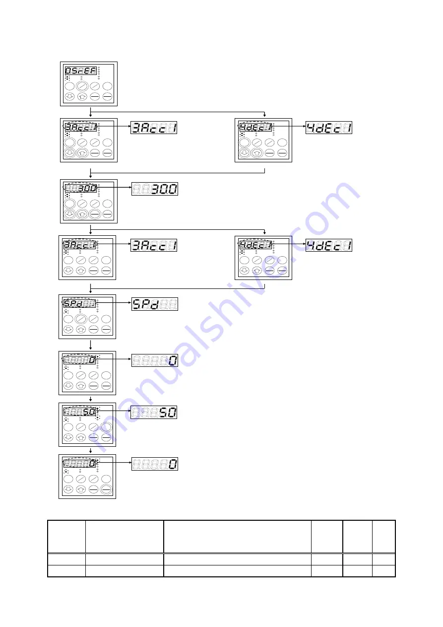
3.3.2.  How to Change the Acceleration/Deceleration time 


r/min 
Hz 
A 
V 

FNC 
DIR 

REV 
ALM 

RUN 
JOG 

FNC 

RESET 

FWD 

JOG 

START 

STOP 

REV 

MONI 

SET 

→ 

When the FNC (LED) on the console panel [SET66-Z] is turned off, press the [MONI/FNC] key to turn on 
the FNC (LED). 


r/min 
Hz 
A 
V 

FNC 
DIR 

REV 
ALM 

RUN 
JOG 

FNC 

RESET 

FWD 

JOG 

START 

STOP 

REV 

MONI 

SET 

→ 

Use the [

] and [

] keys to select “3. 

Acc1” (Acceleration time (1)). Press 
the [SET] key to confirm


r/min 
Hz 
A 
V 

FNC 
DIR 

REV 
ALM 

RUN 
JOG 

FNC

RESET

FWD 

JOG

START 

STOP 

REV

MONI 

SET

Use the [

] and [

] keys to select “4. 

dEc1” (Deceleration time (1)). 
Press the [SET] key to confirm. 

<Acceleration 

time> 

<Deceleration time> 


r/min 
Hz 
A 
V 

FNC 
DIR 

REV 
ALM 

RUN 
JOG 

FNC 

RESET 

FWD 

JOG 

START 

STOP 

REV 

MONI 

SET 

→ 

Use the [JOG/

] key to move the operation digit to the right, use the [

] and [

keys to change the numbers (Acceleration time/Deceleration time), and press the 
[SET] key to confirm. 
*The setting range


is from 0.0 to 3600.0 [s]. 


r/min 
Hz 
A 
V 

FNC 
DIR 

REV 
ALM 

RUN 
JOG 

FNC 

RESET 

FWD 

JOG 

START 

STOP 

REV 

MONI 

SET 

→ 

After confirming the Acceleration 
time with the [SET] key, “3. Acc1” is 
displayed again. 


r/min 
Hz 
A 
V 

FNC 
DIR 

REV 
ALM 

RUN 
JOG 

FNC

RESET

FWD 

JOG

START 

STOP 

REV

MONI 

SET

<Acceleration 

 time>


<Deceleration time> 

After confirming the Deceleration 
time with the [SET] key, “4. dEc1” is 
displayed again. 


r/min 
Hz 
A 
V 

FNC 
DIR 

REV 
ALM 

RUN 
JOG 

FNC 

RESET 

FWD 

JOG 

START 

STOP 

REV 

MONI 

SET 

→ 

Press the [MONI/FNC] key to turn off FNC (LED). Monitor item, such 
as “SPd,” is displayed for about one second. 


r/min 
Hz 
A 
V 

FNC 
DIR 

REV 
ALM 

RUN 
JOG 

FNC 

RESET 

FWD 

JOG 

START 

STOP 

REV 

MONI 

SET 

→ 

1 sec. 
later


About one second later, the display changes to the data of the 
currently set monitor item 
<The figure on the left shows that the motor speed is “0 [r/min].”>. 


r/min 
Hz 
A 
V 

FNC 
DIR 

REV 
ALM 

RUN 
JOG 

FNC 

RESET 

FWD 

JOG 

START 

STOP 

REV 

MONI 

SET 

→ 

When you press the [START] key, the operation starts. The motor starts 
to rotate and accelerates/decelerates at the set 
Acceleration/Deceleration time. During operation, the data of the 
currently set monitor items is displayed. 
<The figure on the left shows that the motor speed is “50 [r/min].”> 
*Acceleration/Deceleration time can be changed during the operation, 
too. 


r/min 
Hz 
A 
V 

FNC 
DIR 

REV 
ALM 

RUN 
JOG 

FNC 

RESET 

FWD 

JOG 

START 

STOP 

REV 

MONI 

SET 

→ 

When you press the [STOP/RESET] key, the operation stops and the 
rotation of motor stops. 
<The figure on the left shows that the current motor speed is “0 
[r/min].”> 

<Setting range of the Acceleration/Deceleration time/setting resolution/initialized data/unit> 

Console 

panel 

Use monitor 

display 

Contents 

Setting range 

(Selecting item) 

Setting 

resolution 

Initialized 

data 

Unit

3.Acc1 

Acceleration time (1) 

0.0 to 3600.0 

0.1 

30.0 

sec

4.dEc1 

Deceleration time (1) 

0.0 to 3600.0 

0.1 

30.0 

sec

Summary of Contents for VF66

Page 1: ...TOYO INTELLIGENT INVERTER VF66B DC motor drive Operating Manual...

Page 2: ...motor drive provides many other features You can build an optimal system for different applications by using its various functions In such a case preferentially use the values described in the dedica...

Page 3: ...ngerous situation medium level or minor injury may result and only physical damage may result However it can cause serious results depending on the situation Cautions described in this manual are all...

Page 4: ...he front cover before turning on the input power Do not remove the front cover during energization Otherwise it can result in a risk of electric shock Do not use the switches with wet hands Otherwise...

Page 5: ...e may occur Do not perform maintenance and inspection or replace parts except qualified persons Use a tool for insulation for maintenance and inspection Otherwise electric shock or injury may occur Wa...

Page 6: ...itor Items 20 3 3 How to Perform Trial Operation 23 3 3 1 How to Change the Motor Speed 24 3 3 2 How to Change the Acceleration Deceleration time 25 3 3 3 How to Change the Rotation Direction 26 3 3 4...

Page 7: ...Area J Communication Setting Area 104 7 12 Area L Setting Area for Analog Input and Output Gain 106 7 13 Area n VF66B DC motor drive Mode Area 108 7 14 Area o Special Adjustment Area 109 7 15 Area P...

Page 8: ...g Package Check that the package contains the VF66B DC motor drive body and the Precautions VF66B DC motor drive body Precautions 2 Check that the specifications accessories spare parts and options ar...

Page 9: ...DC motor drive correctly read this manual completely TOYO VF66B DC motor drive is not designed and produced for the purpose of being used for a device or system under a situation where human life may...

Page 10: ...rive protection contact Note 1 You can change the control input terminal ST F and multifunction input terminals MI1 to MI5 to GND common input sync input In this case remove a jumper socket on the pri...

Page 11: ...hermal relay Collector terminal for the built in dynamic braking DB transistor It is provided for models below 22 kW Connect the dynamic braking DB optional unit VFDB2009 Connect a minus side terminal...

Page 12: ...input current 3 mA Like from the concole panel SET66 Z you can operate the VF66B DC motor draive by inputting asignal into the multifunction input terminals Caution Do not connect the terminal GND to...

Page 13: ...ltifunction input terminal 3 function selection should be set to the field loss signal c 03 13 For the details refer to 6 4 Area c in Chapter 6 and 7 4 Area c in Chapter 7 This is used to detect the V...

Page 14: ...to connect the voltage input to the field amplifier refer to 2 3 How to Connect the Printed Control Board VFC66 Z and Field Amplifier in Chapter 2 2 4 3 Selection of LC Filter Following L DC reactor a...

Page 15: ...cates whether each PG attached to the existing products can be applied PG type Manufacturer Model Applicability Remarks Electromagnetic type ONO SOKKI CO LTD MP837 x Not applicable because of AC outpu...

Page 16: ...SET66 Z 1 5sec 2 Thenthemodel isdisplayedfor1 5seconds Tworightmostdigitsindicatethe feedingvoltage Whenthevoltageclassis 200Vclass 22 isdisplayed Whenit is 400Vclass 44 isdisplayed 1 Themodeisdispla...

Page 17: ...tandard device With this console panel you can operate the unit read and write each function setting data monitor the operating state and display what are protected during protection operations 3 2 1...

Page 18: ...election FNC function setting mode Increases the number indicated in the selected digit by 1 when setting the setting number and setting data Numbers change in this order 0 1 9 minus 0 In MONI monitor...

Page 19: ...the MONI FNC key Press the MONI FNC key In protection display mode Following actions are taken when protection operation occurs Displays the protection operation Performs the one point traceback disp...

Page 20: ...or item r min MONI About one second later the display changes to data display of the currently set monitor item The figure on the left shows that the motor speed SPd is 0 r min 1 sec later r min MONI...

Page 21: ...the analog input of VF66B DC motor drive For the details of how to set the field current refer to 6 2 Area A in Chapter 6 and 7 2 Area A in Chapter 7 10 Overload protection Counter Displays a counter...

Page 22: ...displayed The example above indicates that MI11 is ON 16 Input terminal check 4 Displays the state of the following terminals on the optional board MI15 Multifunction input terminal 15 MI16 Multifunc...

Page 23: ...s of the setting value of cumulative operation timer 2 refer to 6 7 Area F in Chapter 6 and 7 7 Area F in Chapter 7 22 Main unit version Displays the version of the main unit program Example In case o...

Page 24: ...details refer to Chapter 3 3 3 1 How to Change the Motor Speed and the subsequent sections Set motor constant Select the operation commanding place Setting change Press the MONI FNC key on the console...

Page 25: ...d during the operation too r min MONI When you press the STOP RESET key the operation stops and the rotation of motor stops The figure on the left shows that the current motor speed is 0 r min r min M...

Page 26: ...FNC LED Monitor item such as SPd is displayed for about one second r min MONI 1 sec later About one second later the display changes to the data of the currently set monitor item The figure on the lef...

Page 27: ...turns on When you press the FWD REV key while REV LED is turned on REV LED turns off 2 By entering the negative command You can change the rotation direction of motor by setting the value of 0 SrEF S...

Page 28: ...The figure on the left shows that the parameter data is set to 1 r min MONI The changed parameter is displayed again The figure on the left shows b 11 because the setting item b 11 is set Press the MO...

Page 29: ...nd input selection Analog input 1 characteristics selection Analog output 1 characteristics selection Area c Multifunction input place selection Area d Acceleration time JOG acceleration time selectio...

Page 30: ...40 msec 9 ASrJ System inertia moment 1 0 to 65535 10 gm2 6 2 Area A Maximum Speed Rated Motor Parameters Setting Area Symbols of Driving ReWrite ReWrite is possible ReWrite is not possible Console pa...

Page 31: ...rive 1 VF66B DC motor drive Varies with the model 1 mH A 20 Rated speed of tachogenerator 100 to 5000 2000 r min A 21 Voltage input to VF66B DC motor drive upon rated speed of tachogenerator 0 00 to 1...

Page 32: ...tion option 1 b 10 Speed armature voltage command input selection 0 Interlock 1 Analog input 1 VFC66 Z TB1 AIN1 2 Console panel SET66 Z 3 Communication option 4 Analog input 2 optional board AIN2 5 Fo...

Page 33: ...it analog input 1 speed voltage upper limit b 18 to analog input 1 speed voltage upper limit b 18 When the operation mode selection is speed control mode i 07 0 The maximum speed A 00 is 100 When the...

Page 34: ...setting block selection 25 Emergency stop Normally close 26 For special adjustment 1 27 Speed voltage commanding terminal block selection 28 Operation command forward rotation STARTF 2 29 Operation co...

Page 35: ...d 11 S pattern rise time 2 0 0 to 60 0 0 1 sec d 12 S pattern acceleration reach time 2 0 0 to 60 0 0 1 sec d 13 S pattern fall time 2 0 0 to 60 0 0 1 sec d 14 S pattern deceleration reach time 2 0 0...

Page 36: ...erse rotation oFF E 04 Simulation mode oFF Without simulation operation on With simulation operation oFF E 05 No function E 06 Restart prohibition time 100 to 999 100 msec E 07 Current control proport...

Page 37: ...th protection operation oFF F 07 Protection relay 86A operation selection upon power failure oFF Without protection operation on With protection operation oFF F 08 Protection retry count setting 0 to...

Page 38: ...pt100 thermocouple TVPT66 Z option 0 G 01 Temperature detection offset adjustment 20 0 to 20 0 0 0 C G 02 Temperature detection gain adjustment 50 0 to 150 0 100 0 G 03 Analog input 2 characteristics...

Page 39: ...A 1 G 12 Analog input 5 characteristics selection 0 0 to 10 V bipolarity 1 0 to 10 V unipolarity 2 No function 3 Pulse train 0 to 150 kHz 1 G 13 Analog output 4 characteristics selection 0 Output volt...

Page 40: ...re current detection polarized 9 Armature current detection absolute value 10 During power failure 11 Overload pre alarm 12 During retrying 13 During reversing 14 Protection code 15 No function 16 In...

Page 41: ...mand input is high speed operation PLCH output 0 i 02 Droop control usage selection oFF Unused on Used oFF i 03 Droop start speed 0 0 to 100 0 Maximum speed A 00 is 100 0 0 i 04 Droop rate changeover...

Page 42: ...le structure proportion gain start speed 0 01 to 100 00 5 00 i 17 Variable structure proportion gain minimum gain percentage 0 to 500 100 i 18 No function i 19 Machanical loss compensation usage selec...

Page 43: ...input 3 to 19 14 J 05 OPCN66 Z output 2 to 12 6 J 06 For special adjustment 1 J 07 OPCN66 Z transmission wait time selection 125kbps 250kbps 500 kbps 1 Mbps 0 0 1 2 3 4 5 6 200 s 200 s 200 s 200 s 200...

Page 44: ...100 0 L 01 Analog input 1 gain 50 00 to 150 00 Adjusted L 02 Analog input 1 offset 50 00 to 50 00 Adjusted L 03 Analog output 1 gain 50 0 to 150 0 Adjusted L 04 Analog output 1 offset 50 0 to 50 0 Adj...

Page 45: ...00 Special adjusted analog output address H for special adjustment 1 0 to 65535 o 01 Special adjusted analog output address L for special adjustment 1 0 to 65535 o 02 Special adjusted SET66 Z output a...

Page 46: ...t 1 adjustment 1 Analog output 1 offset adjustment 2 Analog output 1 gain adjustment S 08 Analog input 2 adjustment 1 Analog input 2 offset adjustment Enter a value 1000 times the analog input 2 volta...

Page 47: ...in the speed armature voltage command input selection b 10 Refer to 6 4 Area b in Chapter 6 and 7 4 Area b in Chapter 7 Forward Reverse JOG speed 1 FJoG 2 rJoG Set the forward or reverse jog speed Set...

Page 48: ...or the belt vibration connected motor and load take the following measures Set a smaller value Change the settings of the ASR cancelation usage selection i 14 and the ASR feed forward usage selection...

Page 49: ...ings of nameplate values of motor Console panel monitor display Contents Setting range selecting item Setting resolution Initialized data Unit A 02 Rated motor capacity Depends on the model 1 Varies w...

Page 50: ...city A 02 to rated motor field current A 07 set each rating shown on the nameplate or data sheet of the motor Be sure to set them because they are used during an operation Set values shown on the moto...

Page 51: ...dance with PG mounted on the motor Incidentally when using a tachogenerator set the rated speed of tachogenerator A 20 and voltage input to VF66B DC motor drive upon rated speed of tachogenerator A 21...

Page 52: ...2 2 80 3744 2 80 4522 2 80 4544 2 80 5522 2 80 5544 2 80 7522 2 80 7544 2 80 9022 2 80 11044 2 80 15022 2 80 16044 2 80 18022 2 80 20044 2 80 25044 2 80 31544 2 80 40044 2 80 50044 2 80 60044 2 80 750...

Page 53: ...fer to the following table 2 Initialized data of the motor armature resistance A 17 and motor armature inductance A 19 vary with the model of VF66B DC motor drive 3 There is no function to be set Tabl...

Page 54: ...44 16 800 0 751 50044 12 400 0 602 60044 11 120 0 382 75044 8 460 0 312 100044 5 947 0 241 Motor armature resistance A 17 In the motor armature resistance A 17 set motor armature resistance wiring res...

Page 55: ...cribed above Voltage input to VF66B DC motor drive upon rated field current A 23 In this parameter set the voltage voltage to be input to VF66B DC motor drive output by DCCT when the field amplifier i...

Page 56: ...the stop speed b 02 and JOG stop speed b 06 set speeds for stopping an operation or JOG operation Free stop Deceleration stop Turning off an operation or JOG command will cause VF66B DC motor drive to...

Page 57: ...nal or the digital communication option command the operation command to the inverter should be kept ON After the inverter stops when you cannot restart it with the operation command kept ON the start...

Page 58: ...ommand is increased Speed voltage command is decreased Started with forward rotation positive voltage operation Operates in forward rotation positive voltage Limits to minimum speed 0 voltage Started...

Page 59: ...manding place for each command in accordance with the combination of settings from the command input when coupled b 09 to JOG command input selection b 12 command input when coupled b 09 0 Terminal bl...

Page 60: ...JOG and FOR REV keys Console panel JOG and FOR REV keys 3 Communication option Communication option JOG command through each communication Communication option JOG command through each communication C...

Page 61: ...ch of forward rotation and reverse rotation When an armature current command exceeds any of these values it is limited to these setting values Incidentally the rated current of VF66B DC motor drive is...

Page 62: ...he characteristics are the setting of the analog input 1 speed voltage upper limit b 18 When 10 V is input the characteristics are the additive inverse of the setting of the analog input 1 speed volta...

Page 63: ...Speed voltage command Figure 2 2 When 0 to 10V is selected Analog input 1 speed voltage lower limit b 19 is less than 0 3 When the analog input 1 characteristics selection is 4 to 20 mA input b 17 2...

Page 64: ...output 6 Calibration 7 Internal monitor 8 For special adjustment 8 1 No function 1 2 6F speed 3 6F calibration Analog output 1 characteristics selection b 21 In this parameter select analog output da...

Page 65: ...six times of a value equivalent to the maximum speed A 00 When using a digital counter type frequency revolution counter divide the frequency of the pulse count by six When using a DC voltmeter the ch...

Page 66: ...ction relay 86A inactive 20 External failure signal 2 Protection relay 86A inactive 21 External failure signal 3 Protection relay 86A inactive 22 External failure signal 4 Protection relay 86A inactiv...

Page 67: ...o 5 of VFC66 Z TB1 MI1 to MI5 are set as the input terminal blocks of functions of multifunction inputs that are set by the multifunction input terminal 1 function selection c 01 to multifunction inpu...

Page 68: ...input 3 Multifunction input 4 Multifunction input 5 4 7 k 4 7 k 4 7 k 4 7 k 4 7 k CN SI CN SO VFC66 Z External power source 12 V to 24 V 4 Sync mode using an external power source Warning Safety notic...

Page 69: ...ltifunction input terminals 1 to 5 VFC66 Z TB1 MI1 to MI5 terminals and the PS terminal VFC66 Z TB1 PS terminal using a screwdriver M3 to turn them on off Detailed list of multifunction input terminal...

Page 70: ...lected to the Speed_command_input_selection b 10 acceleration or deceleration can be controlled through an UP or DOWN command When frequency speed exceeds its upper or lower limit the inverter automat...

Page 71: ...he protection operation perform the protection operation reset To perform the protection reset set either of the STOP RESET key or the multifunction input terminal as the protection reset and then tur...

Page 72: ...e contact is short circuited VF66B DC motor drive urgently stops When the contact is closed is displayed on the console panel 33 Protection reset RESET Setting this signal to ON during the protection...

Page 73: ...ime Deceleration time 0 Acceleration deceleration time 1 Acceleration time 1 3 Acc1 1 Deceleration time 1 4 dEc1 1 1 Acceleration deceleration time 2 Acceleration time 2 5 Acc2 1 Deceleration time 2 6...

Page 74: ...during the s pattern curve In addition to use the s pattern acceleration deceleration function you need to set the s pattern acceleration deceleration usage selection to use d 06 on Note that the s p...

Page 75: ...aximum speed A 00 1 0 r min d 23 Jump speed 2 0 to maximum speed A 00 1 0 r min d 24 Jump speed 3 0 to maximum speed A 00 1 0 r min d 25 Jump speed 4 0 to maximum speed A 00 1 0 r min d 26 Jump speed...

Page 76: ...e MRH lower limit speed d 29 When both of UP and DOWN commands are not input or are input the speed at that time is kept However if the speed is beyond the MRH upper limit speed d 28 or below the MRH...

Page 77: ...ncidentally the settings of the maximum deviation positive d 31 and maximum deviation negative d 32 become the maximum speed A 00 when they are set to 100 7 6 Area E Current Control Gain Output Voltag...

Page 78: ...C motor drive simulates operation mode without outputting voltages Since VF66B DC motor drive does not output anything during operation in simulation mode you can check the sequence connected to VF66B...

Page 79: ...12 become the rated motor armature voltage A 03 when they are set to 100 Setting of limit width of the voltage corresponding to the speed Console panel monitor display Contents Setting range selectin...

Page 80: ...mong DCCTs on the P side and N side whichever its deviation from the armature current command is smaller Output voltage upon rated speed Console panel monitor display Contents Setting range selecting...

Page 81: ...transistor to be turned on even in other than brake mode set a higher value When using this function in combination with a sine wave converter VF61R VF64R set this setting to 360 V 200 V class or 720...

Page 82: ...lative operation time is cumulative operation timer 1 F 04 cumulative operation timer 2 F 05 VF66B DC motor drive counts cumulative operation time in hour When the cumulative operation time exceeds on...

Page 83: ...to OFF after the power is restored and power failure is reset When the Instantaneous power interruption restart b 07 is set to ON after the power is restored power failure is automatically reset to r...

Page 84: ...lution Initialized data Unit F 09 External failure 1 detection delay time 0 0 to 30 0 0 1 0 0 sec F 10 External failure 2 detection delay time 0 0 to 30 0 0 1 0 0 sec F 11 External failure 3 detection...

Page 85: ...Settings of F 15 to F 26 0 1 to 12 Recorded data Dimension Recorded data Dimension ch1 For special adjustment PLC output RAM 1 through 12 Settings of F 15 to F 26 become the selection of output RAM 20...

Page 86: ...hen the speed deviation maximum speed A 00 x speed control error detection speed width positive F 31 or the speed deviation maximum speed A 00 x speed control error detection speed width negative F 32...

Page 87: ...cteristics selection G 03 In this parameter select the type of input characteristics of option AIN2 For more information refer to the Optional Instruction Manual Analog input 2 limit settings optional...

Page 88: ...d G 08 to 100 0 0 1 100 0 G 08 Analog input 3 lower limit speed analog input 3 upper limit speed G 07 to analog input 3 upper limit speed G 07 0 1 0 0 Analog input 3 upper limit speed G 07 analog inpu...

Page 89: ...e of output characteristics of option board AOT3 For more information refer to the Optional Instruction Manual Analog input 4 characteristics selection optional board AIN4 Console panel monitor displa...

Page 90: ...mmand 3 Speed 4 Speed command 5 Internal PLC function 6 Calibration 7 Internal monitor 8 For special adjustment 9 Output voltage 4 to 20 mA 10 Output current 4 to 20 mA 11 Armature current command 4 t...

Page 91: ...the voltage value that is input to analog input 2 of option board AIN2 Analog input 3 AIN3 G 16 3 In Vin displays the voltage value that is input to analog input 3 of option board AIN3 Analog input 4...

Page 92: ...selection 2 H 05 Multifunction output terminal 6 function selection 3 H 06 Speed detection 1 Maximum speed A 00 to maximum speed A 00 1 0 r min H 07 Speed detection 2 Maximum speed A 00 to maximum spe...

Page 93: ...ifunction output terminal For details refer to Multifunction output terminal function description list described later Multifunction Output Terminal 1 Connection P MO1 MO2 COM VFC66 Z Power supply 24...

Page 94: ...the speed exceeds the speed detection 1 2 H 06 H 07 the output is turned on The speed is detected using a signed value instead of an absolute value Speed detection 1 output Speed Speed detection 1 H 0...

Page 95: ...20 V or more is achieved for 400 V class Note that the output is turned off if the VFC66 Z power source is removed Input direct current voltage Motor rated voltage A 03 10 V 200 V class Motor rated v...

Page 96: ...s MO1 MO2 MO3 MO4 Contents MO1 MO2 MO3 MO4 Overcurrent protection ON OFF OFF OFF Speed control error ON ON ON OFF IGBT protection operation OFF ON OFF OFF PG error ON ON ON OFF GAC abnormality OFF ON...

Page 97: ...tion usage selection 0 Unused 1 High speed operation PLCH is ON 2 High speed operation PLCH is ON speed command input is high speed operation PLCH output 0 PLCL function usage selection i 00 If the in...

Page 98: ...the value Note that the droop start speed i 03 becomes the maximum speed A 00 at 100 Droop rate changeover speed i 04 When a speed command becomes more than or equal to a setting of the Droop rate cha...

Page 99: ...Setting range selecting item Setting resolution Initialized data Unit i 07 Operation mode selection 0 Speed control ASR mode 1 Reverse direction priority for speed control ASR and armature current con...

Page 100: ...R and armature current control ACR Armature Current Commanding Place Selection Console panel monitor display Contents Setting range selecting item Setting resolution Initialized data Unit i 08 Armatur...

Page 101: ...he characteristics When inputting the armature current command through the analog voltage the torque exists in the positive side with the negative voltage Set analog input 1 characteristics selection...

Page 102: ...ole panel monitor display Contents Setting range selecting item Setting resolution Initialized data Unit i 14 ASR cancellation usage selection oFF Unused on Used on i 15 ASR feed forward usage selecti...

Page 103: ...on usage selection OFF Unused ON Used OFF i 20 Machanical loss offset amount 0 to 100 1 0 i 21 Gradient of mechanical loss 0 to 100 1 0 Torque command with machanical loss portion deducted can be used...

Page 104: ...armature voltage control i 33 Setting used to specify an armature voltage command value on the console panel for armature voltage control It is enabled when selecting the console panel as a command i...

Page 105: ...onsole panel monitor display Contents Setting range selecting item Setting resolution Initialized data Unit i 37 Armature current acceleration time for current control 0 0 to 60 0 0 1 15 0 sec Armatur...

Page 106: ...pecial adjustment Usually do not set this item Digital communication option selection J 00 With the optional board connected even if the digital communication option selection is set to OFF J 00 0 the...

Page 107: ...its VFDB2009 connected J 15 Select the dynamic braking DB optional unit VFDB2009 for an absolute value Setting a negative value enables VF66B DC motor drive to be stopped the protection relay to be ac...

Page 108: ...to 150 00 0 01 100 00 L 14 Analog input 4 offset 50 00 to 50 00 0 01 0 00 L 15 Analog input 5 gain 50 00 to 150 00 0 01 100 00 L 16 Analog input 5 offset 50 00 to 50 00 0 01 0 00 L 17 Analog output 4...

Page 109: ...ange selecting item Setting resolution Initialized data Unit n 01 VF66B DC motor drive models read only 2r222 through 9022 2r244 through 31544 Equivalent to VF66B DC motor drive rating VF66B DC motor...

Page 110: ...n the console panel monitor Do not change the parameter data from default setting leave it as factory default Usually an error occurs when write is performed 7 15 Area P Internal PLC Function Paramete...

Page 111: ...to How to Clear Protections described later 4 For special adjustment Provided for special adjustment Usually do not set this item 10 to 15 No function 99 For special adjustment Provided for special ad...

Page 112: ...e FNC function selection mode LED FNC is lit 2 Select S 00 using keys Confirm it with the SET key 3 Shift the target digit to the right using the JOG key edit the number with keys to enter 1040 and co...

Page 113: ...rm it with the SET key If communication with the external console panel SET66EX Z is disabled there is no response VtoS is displayed Data is transferred from the VF66B DC motor drive unit to the exter...

Page 114: ...uently confirm it with the SET key If communication with the external console panel SET66EX Z is disabled there is no response StoV1 is displayed Data is transferred from the external console panel SE...

Page 115: ...equently confirm it with the SET key If communication with the external console panel SET66EX Z is disabled there is no response StoV1 is displayed Data is transferred from the external console panel...

Page 116: ...confirm it with the SET key ConP and SurE flash alternately Subsequently confirm it with the SET key If communication with the external console panel SET66EX Z is disabled there is no response ConP is...

Page 117: ...1 the cumulative operation timer 2 count value can be cleared Vdc Adjustment and Analog Gain Offset Automatic Adjustment Console panel monitor display Contents Setting range selecting item Setting res...

Page 118: ...e panel monitor display Contents Setting range selecting item Setting resolution Initialized data Unit S 04 ROM rewrite switch ROM rewrite is enabled by entering 1040 after power on Console panel moni...

Page 119: ...input 4 voltage V Analog input 4 gain adjustment S 13 Analog output 4 adjustment 1 Analog output 4 offset adjustment 2 Analog output 4 gain adjustment S 14 Analog input 5 adjustment 1 Analog input 5 o...

Page 120: ...the terminal block TB1 on the control print board VFC66 Z using the Phillips screwdriver M3 Next cause short circuit between AIN1 and 10 terminals of the terminal block TB1 on the control print board...

Page 121: ...wer supply Otherwise it can result in a risk of electric shock Be sure to turn off VF66B DC motor drive before switching Otherwise it can result in a risk of electric shock Control print board VFC66 Z...

Page 122: ...ctric shock Control print board VFC66 Z terminal block TB1 After pressing the MONI FNC key to enter the FNC function selection mode LED FNC is lit select b 17 with JOG keys Confirm it with the SET key...

Page 123: ...ith the SET key Enter 1 using JOG keys and confirm it with the SET key Turn off VF66B DC motor drive open the front cover and cause short circuit between the AIN2 terminal on the optional board and th...

Page 124: ...any value other than 1040 is displayed S 09 is displayed again Confirm it with the SET key Edit the number with JOG keys to enter 1 and confirm it with the SET key S 09 is displayed again After press...

Page 125: ...input contact OFF It starts when the multifunction input specified for the emergency stop B has been disabled 9 Failed fan It starts when the cooling fan of VF66B DC motor drive failed The operation...

Page 126: ...reasons in the last digit shows a number to distinguish errors 23 Charging resistance overheat protection It starts when the charging resistance overheats with a model 7r522 7r544 or lower 24 Setting...

Page 127: ...unit becomes more than or equal to a specified value 35 Unit overheat N side master unit It starts when the temperature of cooling heat sink of the N side IGBT in the master unit becomes more than or...

Page 128: ...comes more than or equal to a specified value 49 Blown fuse slave unit 1 It starts when the fuse of the main circuit direct current part in the slave unit 1 is blown 50 Failed fan slave unit 1 It star...

Page 129: ...lave unit 2 It starts when the cooling heat sink temperature of the converter in the slave unit 2 becomes more than or equal to a specified value 66 Gate board communication abnormality slave unit 3 I...

Page 130: ...2 dynamic braking unit 2 is in the protection state or has a communication abnormality 1 The operation is not stopped for protection 80 VFDB3 dynamic braking unit 3 abnormality It starts when the VFDB...

Page 131: ...how to take actions Reference 1 Data was written incorrectly to the EEPROM built in memory due to too much noise Take measures against noise for a wiring from the printed control board VFC66 Z 2 An un...

Page 132: ...drive failed Check the cooling fan of VF66B DC motor drive Contents It starts when the cooling fan of VF66B DC motor drive failed The operation is not stopped for protection Console LED display Cause...

Page 133: ...e the cooling fan 8 The wind of the cooling fan blows in the reverse direction Install the cooling fan so that the wind blows in the correct direction 9 The main circuit printed board GAC66 Z or MAC66...

Page 134: ...he motor 5 The setting of the current control gain is not correct Adjust the current control proportion gain E 07 and the current control integral gain E 08 Chapter 6 6 6 Area E Chapter 7 7 6 Area E 6...

Page 135: ...protection pre alarm operation level setting H 11 Chapter 6 6 9 Area H Chapter 7 7 9 Area H Console LED display Cause Where to check and how to take actions Reference 1 The digital communication optio...

Page 136: ...ed exceeds the forward overspeed protection setting F 01 or the reverse overspeed protection setting F 02 3 The load is smaller than the armature current command value while the armature current contr...

Page 137: ...on starts when the direct current voltage is 200 V class approximately 400 V 400 V class approximately 800 V 4 The dynamic braking DB optional unit VFDB2009 is not operating Replace the dynamic brakin...

Page 138: ...PG Console LED display Cause Where to check and how to take actions Reference 1 It starts due to instantaneous reduction of the control power supply 5 V etc Check the connection of CN1 of the printed...

Page 139: ...tive F 31 and the speed control error detection speed width negative F 32 Chapter 6 6 7 Area F Chapter 7 7 7 Area F 2 The armature current limit was activated because the load was large Reduce the loa...

Page 140: ...malfunctions Check the operation of the communication master Contents It starts when the communication time out error occurs between the communication optional printed board and the communication mast...

Page 141: ...LED display Cause Where to check and how to take actions Reference 1 The protection indicated in No 30 or later is activated Clear the protection operation indicated in No 30 or later Chapter 8 8 1 1...

Page 142: ...y occurs in a communication between the printed control board VFC66 Z and the master unit and the slave unit gate printed board GAC66 Z A character in the second digit from the right distinguishes a m...

Page 143: ...on time is too short Make the acceleration and deceleration time longer 4 Load capacity is abnormally large Motor was direct connect started Reduce the load Review the capacity of VF66B DC motor drive...

Page 144: ...panel and ventilate Contents This function is applied to models 7522 7544 and higher and the unit parallel models It starts when the temperature of the cooling heat sink of IGBT in the unit becomes mo...

Page 145: ...o take actions Reference 1 The output electrical wire was grounded or short circuited Check the output wiring Chapter 2 2 1 How to Connect VF66B DC motor drive 2 The acceleration and deceleration time...

Page 146: ...tly Console LED display Cause Where to check and how to take actions Reference 1 The main cooling fan of VF66B DC motor drive failed Check the main cooling fan of VF66B DC motor drive and replace it 2...

Page 147: ...oard GAC66 Z malfunctions Replace the gate printed board GAC66 Z of the displayed slave unit Contents Applied to the parallel models only It starts when voltage of the control power supply in the slav...

Page 148: ...nal Instruction Manual Contents Applied to the parallel models only It starts when a direct current part overvoltage occurs in the slave unit Protection starts when the direct current voltage is 200 V...

Page 149: ...to check and how to take actions Reference 1 The cooling fan of the converter unit fails Replace the cooling fan 2 The cooling space of the converter unit is not enough Keep enough cooling space Cont...

Page 150: ...1 3 What Are Displayed in Case of Setting Error As to the settings of A 00 through A 07 check each rated value indicated on the name plate of the motor you use or the data sheet For the details of eac...

Page 151: ...F66B DC motor drive model and the motor s rating name plate value and to perform the gain adjustment of the analog circuit part 9 2 Replace the Printed Control Board VFC66 Z Warning Replacing the Prin...

Page 152: ...circles on Figure 1 you can find supports which fix the optional board to the housing of VF66B DC motor drive Remove the optional board by pushing the pawl part shown in Figure 4 into the support Figu...

Page 153: ...tional board by pushing the knob down as shown in Figure 3 b and insert into the connector CN7 and CN4 of the printed control board VFC66 Z respectively When the connectors are attached they will look...

Page 154: ...ET key here you can interrupt the initialization 4 S 00 is displayed again Press the SET key to confirm 5 Use the JOG FWD REV and keys to enter 1 and press the SET key to confirm Message is displayed...

Page 155: ...n it occurs 5 Operating state load state ambient condition date of purchase operation condition 6 Distributor name and the signature of the sales department TB1 CN SO CN SI RY1 CN3 SW2 SW1 CN4 LED1 52...

Page 156: ...ed by you or your customer 3 When the problem was caused by deficiencies in a program created by you or your customer 4 When the problem originated in something other than the delivered product 5 When...

Page 157: ...Denki shall not be responsible for onsite test operation and adjustments All Rights The copyright of this manual belongs to Toyo Denki Duplicating all or part of contents of this manual without obtain...

Page 158: ...e changed without a preliminary announcement by specification change of a product etc Please understand that it may differ from the contents of the operation manual enclosed by the model of purchase a...

Reviews: