100
- For communication option (i-08=2):
Armature current command serves as the input for communication option.
- For internal PLC function (high speed operation PLCH) (i-08=3):
Armature current command serves as the input for internal PLC function (high speed operation PLCH).
- For console panel (i-08=4):
Armature current command serves as the input for the console panel [SET66-Z].
*1: Set analog input (1) characteristics selection or analog input (2) characteristics selection to 0 through ±10 V (b2-17=0,
G-03=0) if selecting analog input (1) (i-08=0) or analog input (2) (i-08=1) in the armature current commanding place
selection. For the armature current command characteristics when selecting analog input (1) (i-08=0) or analog (2)
(i-08=1), refer to figure shown in the description of the analog input armature current command gain (i-09).
Analog Input Armature Current Command Gain
Console
panel
monitor
display
Contents
Setting range (selecting item)
Setting
resolution
Initialized
data
Unit
i-09
Analog input armature current
command gain
50.0 to 200.0
0.1 150.0
%
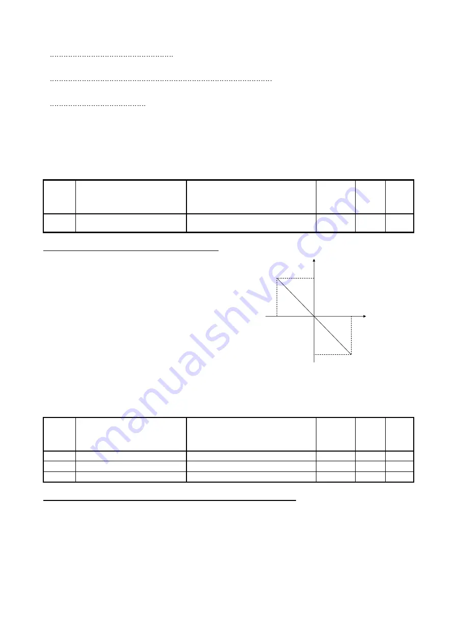
Analog input armature current command gain (i-09):
This is the armature current command gain setting against
the analog input. The right figure shows the characteristics.
When inputting the armature current command through the
analog voltage, the torque exists in the positive side with
the negative voltage.
* Set analog input (1) characteristics selection or analog
input (2) characteristics selection to 0 through ±10 V
(b2-17=0, G-03=0) if selecting analog input (1) (i-08=0)
or analog input (2) (i-08=1) in the armature current
commanding place selection.
Note that if the analog input armature current command
gain is set to 100.0% (i-09=100.0), the torque command
becomes -100.0% at input voltage of 10 V.
(i-09)
-(i-09)
10V
-10V
Input voltage
[V]
Armature current command [%]
(i-09): 50.0 to 200.0 [%]
Analog input armature current
command gain
Changing Speed Control Gain When JOG
Console
panel
monitor
display
Contents
Setting range (selecting item)
Setting
resolution
Initialized
data
Unit
i-10
Speed control proportion gain (2)
1 to 100
1
15
-
i-11
Speed control integral constant(2)
20 to 10000
1
40
msec
i-12
System inertia moment (2)
0 to 65535
1
10
gm
2
Speed control proportion gain (2) (i-10) to system inertia moment (2) (i-12):
If setting the JOG proportion gain selection to "speed control proportion gain (2) (i-10) to system inertia
moment (2) (i-12)" (i-13=1), it is speed control proportion gain used in JOG. For the speed control proportion
gain, refer to the speed control proportion gain setting in "6.1. Basic Setting Area" in Chapter 6 and "7.1. Basic
Setting Area" in Chapter 7.