13
© February 2007 TOSHIBA TEC CORPORATION All rights reserved
e-STUDIO167/207/237
FUSER / EXIT UNIT
13 - 21
[J]
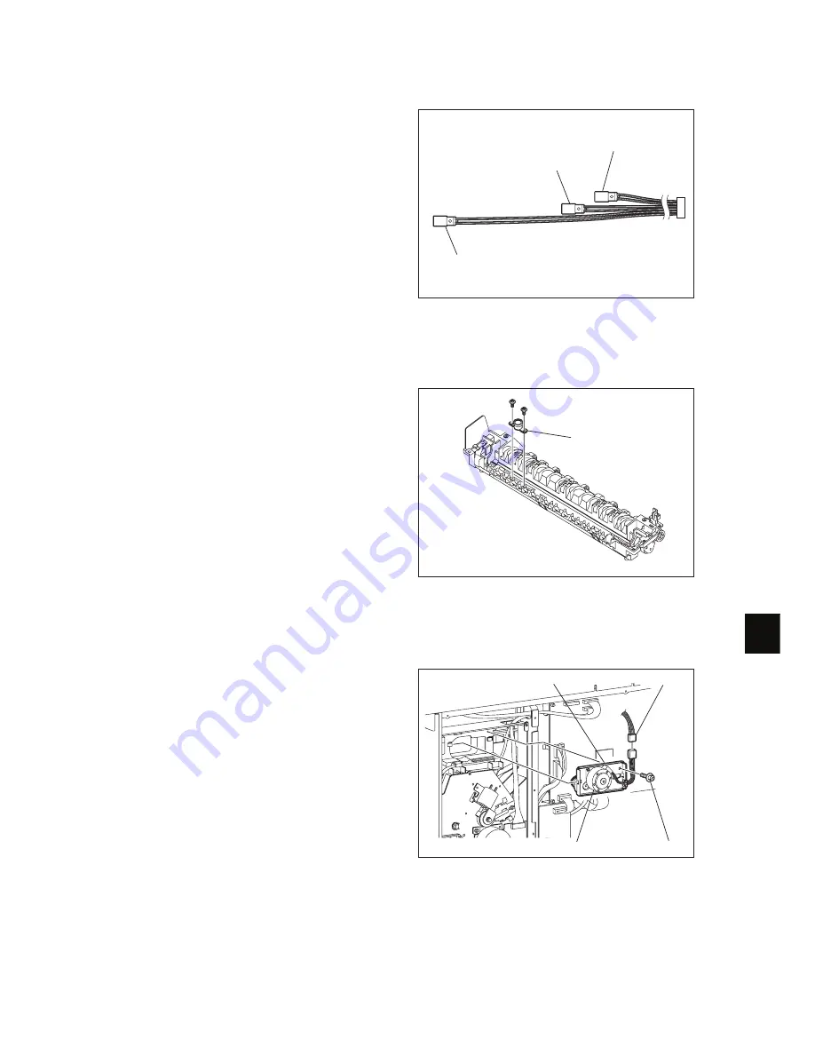
Fuser thermostat (THMO1)
[K] Exit motor (M7): Option
Note:
When installing the thermistors, do not mix
up the installation positions of the side ther-
mistor and the edge thermistor by telling
them apart by the length of their harnesses.
Fig. 13-32
(1)
Take off the fuser roller.
"
P.13-18 "[G] Fuser roller"
(2)
Remove 2 screws and take off the fuser ther-
mostat.
Fig. 13-33
(1)
Take off the rear cover.
"
P.2-22 "[J] Rear cover"
(2)
Disconnect 1 connector, remove 1 screw,
and then take off the exit motor with the
bracket while sliding it toward the right.
Fig. 13-34
Center thermistor
Side thermistor
Edge thermistor
Fuser thermostat
Connector
Bracket
Exit motor
Screw


