


11
© February 2007 TOSHIBA TEC CORPORATION All rights reserved
e-STUDIO167/207/237
DRUM RELATED SECTION
11 - 7
11.5
Drum Temperature Detection Circuit
11.5.1
General description
To prevent the print quality from varying depending on the temperature, the temperature of the drum
surface and around the drum is detected by the drum thermistor. Based on the result of the detection,
this circuit corrects the output of the main charger bias, developer bias, transfer bias and separation
bias as well as the output of the auto-toner sensor and the laser.
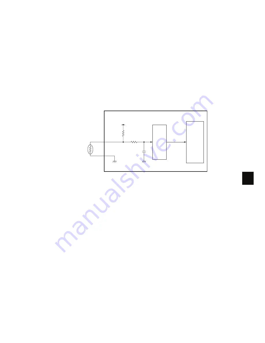
11.5.2
Circuit configuration
The configuration of the drum surface temperature detection circuit is shown below. The voltage output
from the drum thermistor is converted by the A/D converter in the Main board and is input into the SoC.
The drum thermistor is a device whose resistance decreases as the temperature rises; thus, the volt-
age input to the A/D converter becomes smaller along with the rise of the temperature.
Fig. 11-4
Drum thermistor
MAIN board
+5V
SG
SG
DRTH-1A
A/D
converter
Digital
data
SoC