


g014973
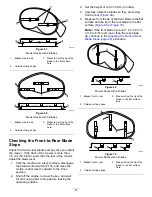
Figure 61
1.
Blade (in position for measuring)
2.
Level surface
3.
Measured distance between blade and the surface (A)
4.
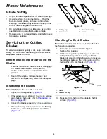
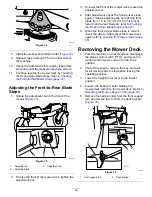
Rotate the same blade 180 degrees so that
the opposing cutting edge is now in the same
position (
g014974
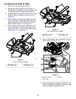
Figure 62
1.
Blade (side previously measured)
2.
Measurement (position used previously)
3.
Opposing side of blade being moved into measurement
position
5.
Measure from the tip of the blade to the flat
surface (
).
Note:
The variance should be no more than
3 mm (1/8 inch).
g014973
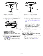
Figure 63
1.
Opposite blade edge (in position for measuring)
2.
Level surface
3.
Second measured distance between blade and surface (B)
A.
If the difference between A and B is greater
than 3 mm (1/8 inch), replace the blade with
a new blade; refer to
(page 45)
and
Installing the Blades (page
.
Note:
If a bent blade is replaced with a
new blade, and the dimension obtained
continues to exceed 3 mm (1/8 inch), the
blade spindle could be bent. Contact an
Authorized Service Dealer for service.
B.
If the variance is within constraints, move to
the next blade.
6.
Repeat this procedure on each blade.
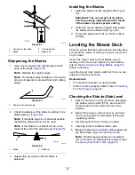
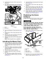
Removing the Blades
Replace the blades if they hit a solid object, or if the
blade is out of balance or bent.
1.
Hold the blade end using a rag or thickly padded
glove.
2.
Remove the blade bolt, curved washer, and
blade from the spindle shaft (
45
Summary of Contents for TimeCutter MX 4275T
Page 2: ......
Page 58: ...Schematics g307974 Electrical Diagram 139 2356 Rev A 56 ...
Page 59: ...Notes ...
Page 60: ...Notes ...
Page 62: ......
Page 71: ...decal140 2748 140 2748 decal142 5864 142 5864 9 ...
Page 121: ...Schaltbilder g307974 Elektrisches Schaltbild139 2356 Rev A 59 ...
Page 131: ...decal140 2748 140 2748 decal142 5864 142 5864 9 ...
Page 180: ...Schémas g307974 Schéma électrique139 2356 Rev A 58 ...
Page 181: ...Remarques ...
Page 238: ...Schema s g307974 Installatieschema139 2356 Rev A 56 ...
Page 240: ......


