


g333873
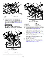
Figure 31
1.
Bypass-lever locations
3.
Lever position for pushing
the machine
2.
Lever position for
operating the machine
5.
Turn the ignition key to the R
UN
position and
disengage the parking brake by moving 1
motion-control lever out of the P
ARK
position.
Note:
Do not start the machine.
6.
Move the machine as required.
Important:
Always push the machine by
hand. Do not tow the machine, because
towing may damage it.
7.
Move the motion-control levers outward to the
P
ARK
position.
8.
Turn the key to the O
FF
position and remove it to
avoid draining the battery charge.
9.
Move both bypass levers rearward and down
through the slotted hole to lock them in place.
Transporting the Machine
Use a heavy-duty trailer or truck to transport the
machine. Use a full-width ramp. Ensure that the trailer
or truck has all the necessary brakes, lighting, and
marking as required by law. Please carefully read all
the safety instructions. Knowing this information could
help you or bystanders avoid injury. Refer to your
local ordinances for trailer and tie-down requirements.
WARNING
Driving on the street or roadway without
turn signals, lights, reflective markings, or a
slow-moving-vehicle emblem is dangerous
and can lead to accidents, causing personal
injury.
Do not drive the machine on a public street
or roadway.
Selecting a Trailer
WARNING
Loading a machine onto a trailer or truck
increases the possibility of tip-over and could
cause serious injury or death (
•
Use only a full-width ramp; do not use
individual ramps for each side of the
machine.
•
Do not exceed a 15-degree angle between
the ramp and the ground or between the
ramp and the trailer or truck.
•
Ensure that the length of the ramp is at
least 4 times as long as the height of the
trailer or truck bed to the ground. This
ensures that the ramp angle does not
exceed 15 degrees on flat ground.
28
Summary of Contents for TimeCutter MX 4275T
Page 2: ......
Page 58: ...Schematics g307974 Electrical Diagram 139 2356 Rev A 56 ...
Page 59: ...Notes ...
Page 60: ...Notes ...
Page 62: ......
Page 71: ...decal140 2748 140 2748 decal142 5864 142 5864 9 ...
Page 121: ...Schaltbilder g307974 Elektrisches Schaltbild139 2356 Rev A 59 ...
Page 131: ...decal140 2748 140 2748 decal142 5864 142 5864 9 ...
Page 180: ...Schémas g307974 Schéma électrique139 2356 Rev A 58 ...
Page 181: ...Remarques ...
Page 238: ...Schema s g307974 Installatieschema139 2356 Rev A 56 ...
Page 240: ......


