


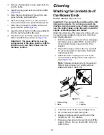


Drive System
Maintenance
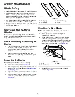
Checking the Tire Pressure
Service Interval:
Every 25 hours—Check tire
pressure.
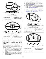
Maintain the air pressure in the front and rear tires as
specified. Uneven tire pressure can cause an uneven
cut. Check the pressure at the valve stem (
).
Check the tires when they are cold to get the most
accurate pressure reading.
Inflate the front caster wheel tires to 206 kPa (30 psi)
or the pressure indicated on the sidewall, whichever
is lower.
Inflate the rear drive-wheel tires to 90 kPa (13 psi).
g000554
Figure 52
1.
Valve stem
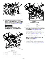
Releasing the Electric
Brake
You can manually release the electric brake by
rotating the link arms forward. Once the electric brake
is energized, the brake resets.
1.
Turn the key to the
OFF
position and remove
the key.
2.
Disconnect the battery.
3.
Loosen the bottom 2 bolts holding the
mower-deck curtain to the mower deck. Refer to
Releasing the Mower-Deck Curtain (page 32)
.
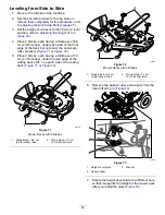
4.
Locate the shaft on the electric brake where the
brake link arms are connected (
5.
Rotate the shaft forward to release the brake
as shown in
.
6.
Rotate the shaft back and connect the battery
after moving the machine.
7.
Tighten the bottom 2 bolts for the mower-deck
curtain to the mower deck. Refer to
the Mower-Deck Curtain (page 32)
.
g294417
Figure 53
1.
Brake-link arm on the electric brake control module
2.
Left, rear tire
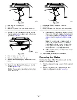
Adjusting the Tracking
When driving the machine forward full speed across
a flat, level surface, if the machine pulls to 1 side,
adjust the tracking.
If the machine pulls to the left, adjust the right
motion-control lever; if the machine pulls to the right,
adjust the left motion-control lever.
Note:
You can adjust the tracking only for driving
forward.
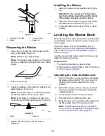
1.
Park the machine on a level surface, disengage
the blade-control switch, and move the
motion-control levers outward to the P
ARK
position.
41
Summary of Contents for TimeCutter MX 4275T
Page 2: ......
Page 58: ...Schematics g307974 Electrical Diagram 139 2356 Rev A 56 ...
Page 59: ...Notes ...
Page 60: ...Notes ...
Page 62: ......
Page 71: ...decal140 2748 140 2748 decal142 5864 142 5864 9 ...
Page 121: ...Schaltbilder g307974 Elektrisches Schaltbild139 2356 Rev A 59 ...
Page 131: ...decal140 2748 140 2748 decal142 5864 142 5864 9 ...
Page 180: ...Schémas g307974 Schéma électrique139 2356 Rev A 58 ...
Page 181: ...Remarques ...
Page 238: ...Schema s g307974 Installatieschema139 2356 Rev A 56 ...
Page 240: ......


