


Lubrication
Greasing the Bearings
Service Interval:
Every 25 hours—Grease the caster
wheel bearings (more often in sandy
soil conditions).
Grease Type:
No. 2 lithium grease
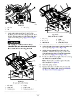
1.
Park the machine on a level surface, disengage
the blade-control switch, and move the
motion-control levers outward to the P
ARK
position.
2.
Shut off the engine, remove the key, and wait
for all moving parts to stop before leaving the
operating position.
3.
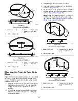
Clean the grease fittings (
) with a rag.
Note:
Scrape any paint off the front of the
fitting(s).
g032432
Figure 37
1.
Front caster tire
4.
Connect a grease gun to each fitting (
).
5.
Pump grease into the fittings until grease begins
to ooze out of the bearings.
6.
Wipe up any excess grease.
Engine Maintenance
Engine Safety
•
Keep your hands, feet, face, other body parts,
and clothing away from the muffler and other hot
surfaces. Allow engine components to cool before
performing maintenance.
•
Do not change the engine governor speed or
overspeed the engine.
Servicing the Air Cleaner
Service Interval:
Every 25 hours—Clean the
air-cleaner foam element (more
often in dusty, dirty conditions).
Every 100 hours—Replace the air-cleaner foam
element (more often in dusty, dirty conditions).
Note:
Service the air cleaner more frequently (every
few hours) if operating conditions are extremely dusty
or sandy.
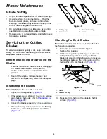
Removing the Foam and Paper
Elements
1.
Park the machine on a level surface, disengage
the blade-control switch, and move the
motion-control levers outward to the P
ARK
position.
2.
Shut off the engine, remove the key, and wait
for all moving parts to stop before leaving the
operating position.
3.
Clean around the air-cleaner cover to prevent
dirt from getting into the engine and causing
damage.
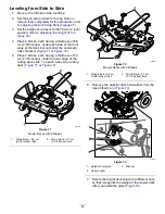
4.
Rotate the latches outward and remove the
cover to access the air-cleaner elements.
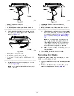
g333875
Figure 38
1.
Latch
3.
Air-cleaner elements
2.
Engine
4.
Air-cleaner base
33
Summary of Contents for TimeCutter MX 4275T
Page 2: ......
Page 58: ...Schematics g307974 Electrical Diagram 139 2356 Rev A 56 ...
Page 59: ...Notes ...
Page 60: ...Notes ...
Page 62: ......
Page 71: ...decal140 2748 140 2748 decal142 5864 142 5864 9 ...
Page 121: ...Schaltbilder g307974 Elektrisches Schaltbild139 2356 Rev A 59 ...
Page 131: ...decal140 2748 140 2748 decal142 5864 142 5864 9 ...
Page 180: ...Schémas g307974 Schéma électrique139 2356 Rev A 58 ...
Page 181: ...Remarques ...
Page 238: ...Schema s g307974 Installatieschema139 2356 Rev A 56 ...
Page 240: ......


