


2.
Shut off the engine, remove the key, and wait
for all moving parts to stop before leaving the
operating position.
3.
Locate the tracking-adjustment bolt near the
motion-control lever on the particular side that
needs adjusting (
).
Note:
Raise the seat for easier access to the
adjustment bolt.
4.
Rotate the bolt to decrease the speed for that
particular wheel.
Note:
Rotate the bolt a small amount to make
minor adjustments.
g294926
Figure 54
1.
Bolt
5.
Start the machine and drive forward across a
flat, level surface with the motion-control levers
fully forward to check if the machine tracks
straight. Repeat the procedure as needed.
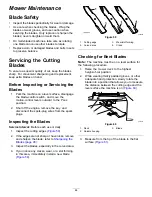
Belt Maintenance
Inspecting the Belts
Service Interval:
Every 25 hours—Check the belts
for wear or cracks.
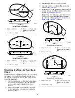
Replace the belt if it is worn. The signs of a worn belt
include squealing while the belt is rotating; the blades
slipping while cutting grass; and frayed edges, burn
marks, and cracks on the belt.
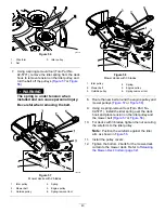
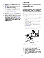
Replacing the Mower Belt
The signs of a worn belt include squealing while the
belt is rotating, blades slipping while cutting grass,
and frayed edges, burn marks, and cracks on the belt.
Replace the mower belt if any of these conditions are
evident.
1.
Park the machine on a level surface, disengage
the blade-control switch, and move the
motion-control levers outward to the P
ARK
position.
2.
Shut off the engine, remove the key, and wait
for all moving parts to stop before leaving the
operating position.
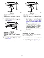
3.
Set the height of cut at the lowest cutting position
(38 mm (1-1/2 inches).
4.
Loosen the bottom 2 bolts holding the
mower-deck curtain to the mower deck. Refer to
Releasing the Mower-Deck Curtain (page 32)
.
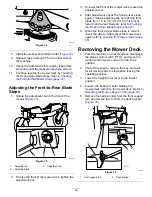
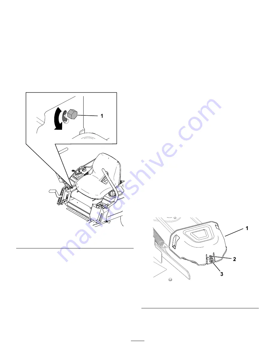
5.
Loosen the screw and push in the tab on the
cover to remove the pulley covers (
).
g296848
Figure 55
1.
Cover
3.
Screw
2.
Tab
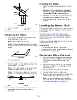
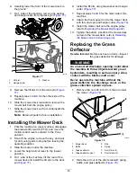
6.
For decks with 3 blades, loosen the nut securing
the wire form to the idler pulley (
42
Summary of Contents for TimeCutter MX 4275T
Page 2: ......
Page 58: ...Schematics g307974 Electrical Diagram 139 2356 Rev A 56 ...
Page 59: ...Notes ...
Page 60: ...Notes ...
Page 62: ......
Page 71: ...decal140 2748 140 2748 decal142 5864 142 5864 9 ...
Page 121: ...Schaltbilder g307974 Elektrisches Schaltbild139 2356 Rev A 59 ...
Page 131: ...decal140 2748 140 2748 decal142 5864 142 5864 9 ...
Page 180: ...Schémas g307974 Schéma électrique139 2356 Rev A 58 ...
Page 181: ...Remarques ...
Page 238: ...Schema s g307974 Installatieschema139 2356 Rev A 56 ...
Page 240: ......


