Appendix 1: Connector Wiring
T
ieline
T E C H N O L O G Y
Page 339
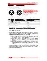
Appendix 1.2.
RTS Headphone Connector
Appendix 1.3.
Codec Connection Cable Configurations
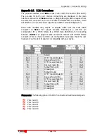
A cable can be constructed using the following components and connections. A
normal D9 to RS 232 modem cable will work well. A null modem cable will not
work at all. Following are the pin and signal configurations for these connectors.
Pin Configurations
Signal
Description
Codec DB 9 male PC DB 9 female
DCE
PC DB 25 female
DCE
TxD
Pin 3
Pin 2
Pin 2
RxD
Pin 2
Pin 3
Pin 3
GnD
Pin 5
Pin 5
Pin 7
For example, if you are connecting your codec using the codec’s
DB 9 male to
the PC DB 9 female, you would connect Pin 2 RxD on the male connector to Pin
2 TxD on the female connector.
Following are diagrams of the pin configurations of the DB9 and DB25
connectors that connect to a codec.
Sleeve
Ring
Tip
Left ear
Right ear
Common

