background image

                                                                                                Section 20: Matrix Editor 

T

ieline


T E C H N O L O G Y 

Page 180

20.9.


Creating, Saving and Amending Matrices 

 
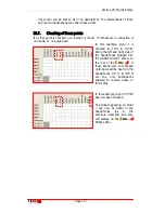
To create a new matrix 

simply click on the 

Edit 

Matrix

 button and click on 

Add

. This will open a new 

menu screen which will 
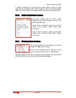
allow you to name the 

matrix.  


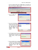
In the example to the left we have called 
it 

Swimming Venue Program

. Names 

can be amended at a later date by 
clicking on 

Rename

 in the 

Edit Matrix


drop-down menu. 


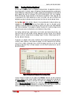
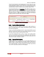
Swimming Venue Program

 will 

now appear as an additional matrix 
in the drop-down 

Matrix

 menu, as 

shown to the left.  


No connection will be checked in 
the matrix initially. You can create 
your matrix from scratch by 

checking the connection signal 
paths you desire. Alternatively, to 

save time you can copy the cross 
point settings from an existing 
matrix to your newly created 

matrix.  


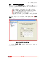
To do this, simply go to the matrix 
you wish to copy from, i.e. 

Manual 

Default Program B

, by selecting it 

with the 

Select Matrix to edit

 drop-

down menu. Once selected, click 

on 

Edit Matrix

 and then 

Copy

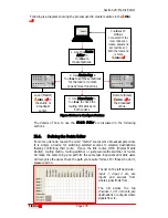
. Then go to the matrix you wish to copy to, i.e. 

Swimming Venue Program

 as shown above, and once selected click on 

Edit 

Matrix

 and then 

Paste

. The cross point connections from the 

Manual Default 

Program B

 matrix will be copied to the 

Swimming Venue Program

 matrix. They 

can be amended as required.  


Summary of Contents for i-Mix G3

Page 1: ...M 600 Integrated Mixer CODEC Main Operation Manual i Mix G3 Reference Manual Version 11 0 Software Version Tieline Toolbox V 4 13 20 RPTP version 99 Firmware Version 1 6 00 RPTP version 99 October 200...

Page 2: ...ION 7 QUICK START CONNECTING QUICKLY USING MANUAL DEFAULT PROFILES 31 7 1 STEP 1 SET AUDIO CONFIGURATION SETTINGS 32 7 2 STEP 2 SELECT A PROFILE 34 7 3 STEP 3 CHANGE CONNECTION SETTINGS 36 7 4 GETTING...

Page 3: ...TIONS 85 10 8 MAKING GSM VOICE CALLS 86 10 9 WHY MAKE GSM VOICE CALLS 86 10 10 SELECTING GSM VOICE MODE 87 10 11 A FINAL NOTE ON GSM CONFIGURATION 89 SECTION 11 3GIP 90 SECTION 12 SATELLITE 91 12 1 BR...

Page 4: ...OPERATION 151 17 1 EXTERNAL RELAY BOX 151 17 2 CABLING AND OPERATION DISTANCES 152 17 3 CAN BUS CABLE TERMINATIONS 153 17 4 INPUTS 153 17 5 OUTPUTS 153 17 6 SETUP 153 17 7 DIP SETTINGS 154 17 8 CMOS...

Page 5: ...RESETS 186 21 8 MANUAL DEFAULT MONO PROGRAM 187 21 9 MANUAL DEFAULT MONO IFB 188 21 10 MANUAL DEFAULT STEREO 190 21 11 MANUAL DEFAULT DUAL PROGRAM 191 21 12 MANUAL DEFAULT BONDED MONO 191 21 13 CREATI...

Page 6: ...LANDLINE INTERFACE 236 24 4 OPERATING MODE 237 24 5 GSM LANDLINE PRE BUFFER SECS 237 24 6 GSM LANDLINE BITRATE 237 24 7 MANUAL DEFAULT GSM LANDLINE ALGORITHM 238 24 8 GSM USB 3G MODULE CELLPHONE SETUP...

Page 7: ...28 10 CONTROL MENU ADJUSTING INPUT LEVELS USING TOOLBOX 256 SECTION 29 REMOTE CONTROL TAB 258 29 1 LOCAL AND REMOTE CODEC OPERATION EXPLAINED 258 29 2 REMOTE CONTROL OF INPUT GAINS 259 29 3 PROFILE R...

Page 8: ...EGRATED COMMUNICATIONS WITH A TIELINE BROADCAST CODEC 315 SECTION 34 UNIT OPTIONS 317 34 1 COUNTRY SELECTION 317 34 2 POWERUP CONSOLE 317 34 3 AUTO RECONNECT 318 34 4 AUDIO REFERENCE LEVEL 318 34 5 BO...

Page 9: ...CONNECTION CABLE CONFIGURATIONS 339 APPENDIX 1 4 D9 RS 232 DATA AND INTERFACE CONNECTORS 340 APPENDIX 1 5 D15 X 21 INTERFACE CONNECTOR 340 APPENDIX 1 6 X 21 CONNECTIONS 342 APPENDIX 1 7 XLR 4 PIN POWE...

Page 10: ...NCODER 88 FIGURE 24 THE TIELINE PORTABLE SOLUTIONS RANGE 89 FIGURE 25 X 21 ISDN INTERFACE CONNECTION 93 FIGURE 26 PHONE AUXILIARY INPUT LEVEL CONTROL LCD SCREEN 97 FIGURE 27 NEW POTS G3 MODULE CONNECT...

Page 11: ...N A COMMANDER G3 CODEC 257 FIGURE 73 TOOLBOX REMOTE CONTROL MENU 258 FIGURE 74 TYPICAL REMOTE CONTROL SETUP WITHOUT USING TOOLBOX 259 FIGURE 75 ACTIVE CUE SOFTKEY FUNCTIONS ON THE COMMANDER G3 FIELD U...

Page 12: ...E 10 ALGORITHM CONNECTION BIT RATE TABLE 215 TABLE 11 ISDN NETWORK SETTINGS 243 TABLE 12 INPUT GAIN SETTING OPTIONS 251 TABLE 13 FUNCTIONS MENU CATEGORY MENU 274 TABLE 14 FUNCTIONS MENU SOURCE MENU 27...

Page 13: ...ighting tower at a sports facility water features and drains on golf courses you will be affected by these secondary strikes Damage to personnel and Tieline codecs may occur during thunderstorms even...

Page 14: ...item inward facing arrows inside the square brackets i e Voice G3 to indicate the menu setting the character is used to indicate movement to the next menu item Pots Wizard Setup GSM Landline Algorith...

Page 15: ...ument as a PDF simply click on the hyperlink to go to the destination If you are not viewing it as a PDF to activate the hyperlink place your mouse cursor on the hyperlink hold down the Ctrl key on yo...

Page 16: ...an insignificant 100ms delay This single unit weights only 5lb 2kg and is easily placed in a briefcase and transported as carry on baggage allowing timely and convenient worldwide deployment of prese...

Page 17: ...sing ToolBox software One of the features of the Tieline i Mix G3 platform is the Configuration File System It enables a user to configure the codec with ToolBox software before arriving at a remote b...

Page 18: ...on these areas the Matrix Editor and Profile Editor sections will explain this in more detail The Operation of your Codec section will assist the experienced user to use the codec with a minimum of fu...

Page 19: ...s over GSM plug in modules or cell phones The Phonebook Editor now supports speed dialing numbers and associated profiles both manual default and custom created profiles Phonebook Editor capacity has...

Page 20: ...e for GSM GSM Voice UMTS EVDO and HSDPA connections Codec interoperability using SIP Addition of the high quality low delay Music Plus algorithm Support for IP dial answer without using session data P...

Page 21: ...features outlined in this reference manual supersede the information contained in the previous manual which was titled TLR300B_Commander_G3_Rack_Unit_PLUS_Main_Man_v 4 0 Following is a summary of the...

Page 22: ...MP2 Mono MP2 Stereo MP2 J Stereo Other and Voice G3 algorithms Seamless up and down re negotiation POTS and IP line quality of forward and reverse link displayed on both codecs Programmable automatic...

Page 23: ...please see the section in this reference manual titled GSM Transparent and Non transparent Data Modes For all other data information please see the section of this reference manual titled Data Transfe...

Page 24: ...ck unit codec Important Note It is important to note that the i Mix G3 has several different features in comparison with the COMMANDER G3 Field Unit and Rack Unit codecs For example it has more inputs...

Page 25: ...ection 5 Controls and Connections for the I Mix G3 Tieline Page 25 T E C H N O L O G Y Section 5 Codec Controls and Connections ISDN POTS GSM X 21 3G Expansion slot for interchangeable Tieline modules...

Page 26: ...ut PPM style meter 10 LEDs in 3dB increments Programmable for send or receive audio LCD DISPLAY 4 rows of 20 characters display the menu options MENU SELECTOR MS For navigation through the menu option...

Page 27: ...handle inputs from 72 dB to 18 dBm The MIC LINE inputs have an associated headphone connector input PROGRAM OUT Line level balanced outputs that are programmable with the Tieline ToolBox Can be contr...

Page 28: ...the POTS connection is surrounded by the square brackets so the POTS wizard will open if SOFTKEY 3 is pressed All the previous Tieline menu configuration options are still available by pressing SOFTK...

Page 29: ...the modules are inserted into the rear of the codec Therefore if the following image was from a rack unit codec the arrows would display where the modules are positioned in the rear of the codec when...

Page 30: ...at the remote site One ISDN module which requires one ISDN line with up to two B channels One ISDN line and one POTS module ISDN can be used as the primary link and the POTS line can be used as a bac...

Page 31: ...e into the codec Modules should be installed slowly and gently WARNING Ensure that both the local and remote codecs are connected correctly before use If you plug a digital PBX line into the RJ11 conn...

Page 32: ...manual in hard copy please consult the relevant sections in the elements of this manual relating to ToolBox Input Gains Mic Phantom Power IGC Enable IGC Auto Level Oscillator Enable PPM Meters Audio R...

Page 33: ...Section 7 Quick Start Tieline Page 33 T E C H N O L O G Y 7 1 1 Codec Audio Menu Figure 6 Codec Audio Menu Structure...

Page 34: ...th this profile you can send bi directional mono program audio of up to 15 kHz between two codecs over an analog phone line a GSM cell phone a 3G cell phone an ISDN B channel an X 21 connection or IP...

Page 35: ...ual in hard copy format go to the section titled Manual Default Profiles Manual Default Mono Program Manual Default Mono IFB Manual Default Stereo Manual Default Dual Program Very Important Connection...

Page 36: ...have scrolled to with the MENU SELECTOR or to keep any of the current settings and continue through the wizard Press SOFTKEY 3 Exit to exit the wizard at any time any changes prior to exiting the men...

Page 37: ...Section 7 Quick Start Tieline Page 37 T E C H N O L O G Y 7 3 1 New POTS Wizard Figure 8 POTS Menu Configuration Wizards...

Page 38: ...Section 7 Quick Start Tieline Page 38 T E C H N O L O G Y 7 3 2 New ISDN Wizard Figure 9 ISDN Menu Configuration Wizard...

Page 39: ...Section 7 Quick Start Tieline Page 39 T E C H N O L O G Y 7 3 3 New GSM Wizard Figure 10 GSM Menu Configuration Wizard...

Page 40: ...Section 7 Quick Start Tieline Page 40 T E C H N O L O G Y 7 3 4 New IP Wizard Figure 11 IP Menu Configuration Wizard...

Page 41: ...Section 7 Quick Start Tieline Page 41 T E C H N O L O G Y 7 3 5 3G Wizard Figure 12 3G Wizard...

Page 42: ...Section 7 Quick Start Tieline Page 42 T E C H N O L O G Y 7 3 6 New X 21 Wizard Figure 13 X 21 Menu Wizard...

Page 43: ...S algorithm setting if your program content contains music Voice G3 is generally best to use for a POTS connection if your connection bit rate is 16 800 bps or lower It is a good idea to listen to the...

Page 44: ...MPEG 2 Layer 2 Recommended Bitrates The following tables indicates the connection bitrates that are recommended for MP2 MPEG 2 Layer 2 algorithm connections which are available in Tieline codecs The...

Page 45: ...hannel is adequate for high quality MP2 Stereo connections 2 The connection wizard is the safest way to configure connections This is because in the main connection menu via Menu Configuration ISDN IP...

Page 46: ...4K 128K 192k 256K 16kHz 24kHz 32kHz 48kHz MP2 Stereo 64K 128K 192k 256K 16kHz 24kHz 32kHz 48kHz TLR300B only Table 2 ISDN MPEG 2 Layer 2 Recommended Bitrates 7 3 9 3 Recommended X 21 Bit rates MP2 Mon...

Page 47: ...z MP2 J Stereo 64K 96K 112K 128K 192k 256K 16kHz 24kHz 32kHz 48kHz MP2 Stereo 64K 96K 112K 128K 192k 256K 384K 16kHz 24kHz 32kHz 48kHz TLR300B only Figure 15 IP MPEG 2 Layer 2 Recommended Bitrates Ple...

Page 48: ...nnection Type Algorithm Minimum Bit rate and Bandwidth Recommended Connection for On air use POTS Music Up to 7 5kHz at 9 600 bps3 Up to 15kHz at 24 000 bps POTS Voice G3 7 5 kHz at 9 600 bps Optimize...

Page 49: ...udes a data channel of 50 bytes per second which can be used to send RS232 data between devices attached to the serial port of each Tieline codec It is very important to note that remote control funct...

Page 50: ...MP2 Mono MP2 Dual MP2 Stereo MP2 J Stereo RAW Audio Music Plus POTS ManDflt MonoPgm ManDflt Mono IFB ManDflt Stereo ManDflt DualPgm IP ManDflt MonoPgm ManDflt Mono IFB ManDflt Stereo ManDflt DualPgm 3...

Page 51: ...t MonoPgm ManDflt Mono IFB ManDflt Stereo ManDflt DualPgm Not recommended for use on TLF300 and TLR300 using new POTS G3 Module Table 4 Profile Algorithm and Sample Rate Matrix Tieline G3 Codec Sample...

Page 52: ...Section 7 Quick Start Tieline Page 52 T E C H N O L O G Y 7 3 10 Dual Mono Program Valid Algorithm Combinations Table 5 Dual Mono Program Algorithm Matrix...

Page 53: ...ovide rule of thumb guidance for different connection bit rate settings Please Note The connection procedures described in this Quick Start manual are for manual connections If you wish to use the Tie...

Page 54: ...pressing SOFTKEY 1 Aud If you are not using a microphone at the codec you are dialing from go to step 7 Step 6 The default input level setting is Line Level To adjust input gains press SOFTKEY 1 with...

Page 55: ...the codec reference manual IP Warnings If you connect over IP and use auto jitter buffer then both codecs must have firmware v 1 6 xx installed Unless the remote codec has a public IP address assigne...

Page 56: ...figure the codec serial port for GSM use To configure GSM cell phone connections press SOFTKEY 4 Menu scroll to Configuration Advanced Menu Serial Port Mode GSM This configures the serial port and the...

Page 57: ...installed for UMTS HSDPA networks or provisioned activated for EV DO networks into your codec and then power up the codec 2 Scroll to the 3GIP1 connection with the codec MENU SELECTOR and press SOFTKE...

Page 58: ...croll to Configuration GSM 3G Setup 3G Module Note on Cell phone Use with Tieline USB Modules Turn on your 3G cell phone and wait 30 seconds before you connect the phone to the USB module via its USB...

Page 59: ...c may have a PC connected to it using Tieline ToolBox software The remote codec its companion partner is usually at the broadcast venue or remote site This is usually the slave codec able to be contro...

Page 60: ...Before commencing Remote Control configuration we recommend that you ensure that any previous settings have been deleted from the menus To do this press SOFTKEY 4 Menu on each codec and then scroll t...

Page 61: ...is being used for talkback then this will only work in offline mode Please note that there is no CUE COMMS button on a COMMANDER G3 field unit codec so level adjustment of inputs by this method is not...

Page 62: ...Section 7 Quick Start Tieline Page 62 T E C H N O L O G Y 7 12 Codec Remote Control Menu Structure Figure 17 Remote Control Codec Menus...

Page 63: ...ithms have been developed including well known MPEG layer 2 and 3 These algorithms require a reasonably high bit rate typically 64 kbps or higher for high quality wide band mono operation Many ISDN co...

Page 64: ...nsfer using a process of negotiation Negotiation is the process of bit rate adjustment To negotiate bit rates up press F2 then 3 or for lower bit rates press F2 then 9 The relationship between Line Qu...

Page 65: ...s and data transmission Substitute a normal phone for the fax machine and verify correct operation Use a normal phone not a house supplied phone as the house phone may have characteristics to match th...

Page 66: ...ust bridge into the lower floor IDF leaving the upper floor IDF still connected The unused stub from the lower to upper floors could then cause problems 8 7 Earth Leakage Problems on the Line A good l...

Page 67: ...r own phone when you are doing a remote broadcast If possible dial the number you are going to use and check for any unusual noises These may be due to other devices connected to the line 2 Tieline US...

Page 68: ...the old one because the original DAA module has been removed as displayed in the following image The modules are also named POTS and POTS G3 on the front of the module to distinguish one module from t...

Page 69: ...dules create stable connections because they measure the amount of fluctuation in line quality before working out the optimal bit rate setting to connect at This provides very stable POTS connections...

Page 70: ...is completed the standard connection screen is displayed Figure 21 Standard POTS Connection Screen This is a little different to dialing with the original Tieline POTS module When dialing with this m...

Page 71: ...mlessly if required without the delay of retraining 8 11 5 Dialing from a POTS Module to a POTS or POTS G3 Module Tieline POTS modules initially attempt to establish a link at 19 200 bps They will the...

Page 72: ...e 72 T E C H N O L O G Y Support Tip The Tieline USA POTS test number 317 913 6911 and the codec s Line Quality Display is there to help you test your codec If you need any assistance in setting up yo...

Page 73: ...ch network will you be using Is your ISDN line Point to Point or Point to Multipoint What is your Service Profile ID SPID and what are your Directory Numbers DN1 DN2 What is your Multiple Subscriber N...

Page 74: ...del Tieline Part Number Commander Field TLISDNUS Commander Field TLISDNEU i Mix TLISDNUS i Mix TLISDNEU Table 6 ISDN Modules 9 3 How do I install the ISDN module You can purchase a Tieline codec with...

Page 75: ...nded to provide users with the necessary tools to make successful ISDN calls on Tieline codecs under a variety of ISDN line conditions 9 4 1 Important Settings First it is important to know what Wizar...

Page 76: ...ultipoint are designated by the network service provider and may vary between venues and locations Another ISDN setting is On Demand This may be designated On or Off by the network service provider an...

Page 77: ...el 15db is the default input gain for inputs If you require an alternate input gain press SOFTKEY 1 Audio then select Input Gains All Inputs select desired input level 9 4 7 Configuring ISDN ISDN can...

Page 78: ...number again will result in the following screen with a mix of the inputs received on the De 02 Decoder 2 PPM 9 4 9 On Demand If Sync appears for approximately 60 seconds upon initial connection of th...

Page 79: ...B channels connect at 128kb scroll until ISDN 2 is surrounded by square braces and proceed by following previous steps 2 4 6 When fully connected at 128kb both ISDN B channels will be connected with t...

Page 80: ...a and use either G 722 or MP Layer 2 algorithms for compatibility The following settings must be manually set on both ends Profile Mono Stereo Algorithm Sample Rate Other settings as required by the n...

Page 81: ...es a process called Circuit Switching Circuit switching is a method of communicating where a communications path is established between two devices through one or more switching nodes The digital data...

Page 82: ...Do not force a module into the codec Modules should be installed slowly and gently A Cautionary Note Some service providers package voice and data as a standard subscription and others require you to...

Page 83: ...e connecting via an HSCSD connection up to 15kHz the GSM bit rate and codec algorithm need to be set to 28800bps and Music respectively When you select an HSCSD connection during the configuration pro...

Page 84: ...232 GSM connection on the codec LCD screen using the MENU SELECTOR Then press SOFTKEY 3 Wiz to activate the menu wizard Select OK in the wizard to proceed and then ensure the following wizard setting...

Page 85: ...the following wizard settings are selected Pots Wizard Setup GSM Landline Algorithm Voice G3 GSM Landline Rate 9600 Pre buffer Secs 0 Auto Reconnect Disable Please Note Initially set the Pre Buffer Se...

Page 86: ...hen you use a Nokia 6310i cell phone If your SIM card is set to transparent mode you will be unable to receive any calls to your cell phone or GSM module Contact your telco to check if your SIM card h...

Page 87: ...Analog Signal Strength Enable Enable Auto Reconnect Disable and press OK to complete the configuration Please note The other way to configure a plug in module for voice mode is to select Menu Configu...

Page 88: ...23 Phone Audio Routed to Encoder As displayed in the right hand image phone audio by default is routed to the Send section of the matrix You may recall that the BALANCE knobs on Tieline codecs control...

Page 89: ...a POTS or GSM voice call 10 11 A Final Note on GSM Configuration For more detailed information on configuring your codec and using ToolBox please see the GSM LL GSM section in this reference manual Op...

Page 90: ...ned in the IP 3GIP Streaming Reference Manual which is a separate document This manual contains all the relevant information for streaming audio over IP including SIP connectivity Contact Tieline supp...

Page 91: ...adband Global Area Network BGAN BGAN is a global high speed mobile satellite data network It is capable of sending broadband data at bit rates up to 492 kbps Guaranteed bandwidth rates are offered and...

Page 92: ...The physical interface to a Tieline codec is via a DB15 connector ISO 4903 The pin outs for D 15 X 21 module connections are displayed in the Connector Wiring section of this reference manual A straig...

Page 93: ...ncoming call When dialing from one codec to another the dialing codec DTE1 changes the C Signal from off to on to initiate an outbound call At the codec DTE2 receiving the call an I Signal Indication...

Page 94: ...P connections are contained in the IP 3GIP Streaming Reference Manual which is a separate document This manual contains all the relevant information for streaming audio over IP including SIP connectiv...

Page 95: ...loaded To permanently edit and save any changes to profiles or to create new profiles you must use ToolBox software For a more comprehensive and detailed description of Current Runtime and editing and...

Page 96: ...d be set so that audio peaks average at the first set of orange PPM LEDs Related Topic PPM Displays 15 5 Adjusting Auxiliary and Phone Input Levels The incoming level of the auxiliary and phone inputs...

Page 97: ...cs 2 An audio source e g microphone CD player oscillator etc is connected and that audio levels have been set using either the Aud menu via SOFTKEY 1 on the codec or the Inputs menu within ToolBox 3 H...

Page 98: ...er up the codec the backlight on the LCD SCREEN LCD will be illuminated instantly confirming that power is reaching the codec Wait for about 15 seconds for the unit to start up and load the operating...

Page 99: ...using the same algorithm otherwise your codecs will not operate correctly If you are using manual default profiles when the dialing codec calls the remote codec the dialing codec will automatically s...

Page 100: ...Finally if an ISDN line is attached to the codec and the ISDN card has been read the Network has been detected and it is ready to connect the two B channels connections will display as ISDN1 Enter Sy...

Page 101: ...ia Menu Configuration Advanced Menu IP Stream Demo Enable If you don t have an Ethernet cable attached to the LAN connection of the codec the connections will be displayed as shown in the right hand i...

Page 102: ...e right hand image Simply use the keypad to add the IP address you wish to dial and connect to the other codec This is just like connecting over any IP connection in terms of its functionality 15 11 6...

Page 103: ...sing the POTS module we have installed in the codec In other words the connection displayed as POTS2 Enter If you are confident that the correct POTS profile with all the connection settings you want...

Page 104: ...would simply repeat the procedure for the second POTS connection Related Topics Manual Default Profiles Powerup Profile and POTS Connection Tip Scrolling to an active connection and pressing ENTER DI...

Page 105: ...ighest possible bit rate where line quality is greater than 70 15 12 5 Dialing from a POTS G3 Module to a POTS G3 Module When initially connecting to another POTS G3 module Tieline POTS G3 modules wil...

Page 106: ...bit rate of the connection and the Line Quality of both codecs will be displayed 15 12 7 Unsuccessful POTS Connections If the RJ11 POTS line is not connected to the codec properly the following error...

Page 107: ...e LCD While the codec is dialing it will display as shown in the right hand image By default a Tieline codec receiving a call will auto answer or if this is not programmed the operator will need to pr...

Page 108: ...startup LCD GSMCS1 or GSMCS2 in the example above To select the number you wish to dial either a Press the MEMORY key to get a number from the phone book or b Press the ENTER DIAL key to display the l...

Page 109: ...n menu an LCD screen similar to the right hand one will be displayed To dial in this situation 1 Use the MS to scroll to the 3GIP connection you want on the codec LCD To select the number you wish to...

Page 110: ...play the last dialed IP address for that connection or c Simply dial the IP address for the destination codec using the keypad Note Use the or button on the codec keypad to enter the periods in the IP...

Page 111: ...21 module has a cable attached to a connection from your ISDN TA X 21 DCE Device 2 Press the ENTER DIAL button on the keypad to make the call The connection you are using should then display Connectin...

Page 112: ...profiles you create can be configured for a particular type of connection and you can program the number or the IP address to be dialed into the profile 15 18 1 Operating the Connection Manager On po...

Page 113: ...ver connection to connect along side your main connection also programmed to be inactive unless failover is initiated all programmed connections will be dialed by the Connection Manager when it is act...

Page 114: ...necting Using the Connections Manager If you wish to end a connection simply press SOFTKEY 1 on the main Connections Manager LCD which will have Cxns displayed above it Then press SOFTKEY 2 which will...

Page 115: ...gains Configuration The submenus of this are numerous and cover a broad array of system and connection settings Reset Functions Menu items allow you to reboot the codec or reset codec settings to the...

Page 116: ...Section 15 Operation of your Codec Tieline T E C H N O L O G Y Page 116 Figure 29 Menu Submenus...

Page 117: ...Setup Sets a range of ISDN functions relevant to ISDN use POTS Left Setup POTS Right Setup Sets a range of modem functions relevant to POTS use GSM 3G Setup Sets functions relevant to GSM 3G module an...

Page 118: ...ss The codec Mac address IP Address Displays the relevant IP address for LAN connections Subnet Mask Displays the Subnet Mask for LAN connections Default Gateway Displays the Default Gateway for LAN c...

Page 119: ...Section 15 Operation of your Codec Tieline T E C H N O L O G Y Page 119 Figure 30 Configuration Submenu Items...

Page 120: ...es This menu allows you to select the profile you wish to load in the codec Any custom profiles that are loaded into the codec will also be listed within this menu By pressing either SOFTKEY 1 or 2 yo...

Page 121: ...ed by SOFTKEYS 1 2 Exit Menu Exits the Remote Control menu to the Menu submenu AES Rx Clock Codec sample rate set to the rate of the signal being received by the AES EBU input External Word Clock Conf...

Page 122: ...r automatically limits high input gains Disable Disables IGC Enable Enables IGC Auto Level Default IGC Auto Level The inbuilt DSP limiter automatically lowers high input gains and then returns incomin...

Page 123: ...le Default Disables balanced mono output enables auxiliary output Exit Menu Exits this submenu and goes to the Configuration submenu EU ETSI If Switch Type is ETSI UK Europe Australia and most other c...

Page 124: ...r assigned to each B channel of an ISDN connection It may also be known as the Multiple Subscriber Number MSN Enter Number Point to Point Selects point to point configuration Line Type Selects point t...

Page 125: ...6 000 Sets this sample rate in the codec 24000 Sets this sample rate in the codec 32000 Default Sets this sample rate in the codec Sample Rate Adjusts the sample rate setting in the codec 48000 Sets t...

Page 126: ...By enabling the Detect dial tone function the codec will wait until a dial tone is present before dialling Disable Disables this function Use if there is any difficulty in detecting a dial tone Tone...

Page 127: ...re circuits where the loop voltage is not present Disable Default Disables this function for non leased 2 wire lines Enable Enables this function Quick Negotiation If enabled the modem will attempt to...

Page 128: ...is retrained if line quality at both ends is above 80 Down A lower bit rate is renegotiated if line quality falls below 20 at either end Current The modem will retrain to the current bit rate setting...

Page 129: ...Only one GSM module can be installed in a codec or an error message will be displayed Enable Enables this function Configuration cont GSM 3G Setup Ext CellPhone If you are connecting via a cell phone...

Page 130: ...e Buffer seconds and algorithm for your POTS module For more information please see the GSM LL GSM USB 3G section within this manual GSM Landline Mode Disable Default Disables this function GSM 3G Set...

Page 131: ...to connect over the IP connection Music Plus Selects this algorithm MP2 Mono 16 000 24 000 32 000 48 000 MP2 Dual 16 000 24 000 32 000 48 000 MP2 Stereo 16 000 24 000 32 000 48 000 If you select one o...

Page 132: ...ror correction setting on the local codec Off Default 20 33 50 100 There are five settings in this menu for UDP connections For more info see the IP sections of this manual Remote FEC Percent UDP only...

Page 133: ...ts this algorithm MP2 Dual Selects this algorithm MP2 Stereo Selects this algorithm Algorithm Sets the algorithm in the codec MP2 J Stereo Selects this algorithm 16000 Selects this sample rate 24000 S...

Page 134: ...r Name Enter the SIP user name for the codec Password Enter the SIP password into the codec Reg Refresh Sec Enter the registration refresh setting in seconds The default setting is one hour Auto Defau...

Page 135: ...ent from a codec Session Data This menu can disable and enable session data sent from a codec Disabling session data may assist to connect via G 722 and MPEG algorithms Disable Disables the sending of...

Page 136: ...u choose within this menu will decide which menu screen the codec will display on power up It does not control which profiles are loaded into the codec prior to powering the unit down Last Selected Th...

Page 137: ...ccessfully you must ensure that both your codec and your ToolBox software are configured correctly Related Topic Connecting Your Codec to a PC Data Tells the codec you will be sending data via the ser...

Page 138: ...IP setup allows the user to input the IP addressing information that is necessary when using a LAN connection Exit Menu Exits to the Advanced submenu Enable Enables this function press OK via SOFTKEY...

Page 139: ...this feature Watchdog Enable Enables resetting of codecs automatically if they require this intermittently Disable Disables this feature Default Unit CAN Id Not required for standard setups In some si...

Page 140: ...s delete function Phone Book Entries 1 80 Delete Delete function for the phone entry YES Deletes the number DTMF Control Enter DTMF Digits Firmware Version The software version within the codec RPTP V...

Page 141: ...eway Displays the Default Gateway for LAN connections Time Displays the time set in the codec Date Displays the date set in the codec Build Date Displays the build date of the codec s operating system...

Page 142: ...OR MS to scroll to and select Configuration Advanced Menu Serial Port Mode Data A wizard will then ask an operator to confirm the following 1 The serial port data rate setting default is 9600 and 2 Wh...

Page 143: ...sion data within Tieline codecs following is a diagram of the OSI model of computer network protocol design In the table below the functions of the protocol are divided into layers to describe each el...

Page 144: ...le Please note that this is a global setting and will also affect all POTS and IP connections on the codec If you try to connect to a Tieline codec with session data disabled you will have to ensure t...

Page 145: ...tings are programmed into both codecs This will not only reduce the chance of a failed connection it will also reduce the time it takes for the two codecs to connect If a non Tieline codec is set to a...

Page 146: ...until you see the screen as displayed in the following image Figure 32 Session Data Status Display Some of the other messages you may see in the Session Xfer session include Timeout If session data ti...

Page 147: ...ns Session data should only be disabled if you are having difficulty connecting The default setting enabled should be used in most situations 16 8 Configuring the Serial Port to Send Data By default t...

Page 148: ...bit stream as the audio that is sent between two codecs Simply configure your RS232 connection to send data turn serial port flow control on and you are ready to go If you are connecting over POTS 50...

Page 149: ...line GSM modules only support the sending of non transparent data We also recommend that you use non transparent data mode when you use a Nokia 6310i cell phone If your SIM card is set to transparent...

Page 150: ...via ISDN An ISDN module can be used for DTMF control of a device if the module is used in ISDN voice call mode To program an ISDN module for voice mode simply select the G 711 algorithm and the codec...

Page 151: ...buttons or HOTKEY buttons on the COMMANDER G3 rack unit codec front panel and TLG3 GUI or the i Mix G3 for faster one button operation Please see the ToolBox Functions menu section within this manual...

Page 152: ...e is being used heavier conductors will be required Screw terminal plugs are provided to allow for easy on site wiring These can be hot plugged without any impact upon a unit s performance In general...

Page 153: ...input pin to the ground terminal This can be via a remote relay contact or the open circuit collector of a transistor or FET 17 5 Outputs CMOS field effect transistors switch a low impendence path be...

Page 154: ...or HOTKEY buttons 17 8 CMOS Relay Operational Mode As mentioned the CMOS relays can be set to work in two ways They can pulse ON for one second or they can stay ON until another command is sent to tu...

Page 155: ...and check for the most suitable version to upgrade your codec If you are not sure what version of ToolBox software you should be running regardless of whether you have a new G3 codec or an older G1 l...

Page 156: ...istributed as a compressed file zip file Extract the program file to the PC hard drive using a program such as WinZip Click on this hyperlink to download Winzip or visit www winzip com Once you have u...

Page 157: ...correctly The COM port is set up by ToolBox When you first connect to the codec in order to operate ToolBox effectively you will first need to add the codec to your Devices menu tree The steps to con...

Page 158: ...you are connecting via a USB port to the codec you will need to ensure you have installed the appropriate USB software drivers to connect successfully If you don t have the appropriate USB drivers pl...

Page 159: ...you do not have these drivers please contact us at support tieline com IMPORTANT Each time you connect a new codec to your PC via USB you will need to reinstall the USB software drivers This is becaus...

Page 160: ...is still obtaining a DHCP address it will display the message Requesting IP 18 6 2 Static Addresses Connecting via a Crossover Cable Connection If you are connecting your PC directly to your codec via...

Page 161: ...from your PC to the LAN port on your codec Then click on the Start menu on your computer and select the Control Panel Then select Network Connections Next select your codec LAN connection by right cl...

Page 162: ...ary to configure the codec serial port itself Once you have initially powered up the codec select the Menu option from the startup LCD screen as shown This is done by pressing SOFTKEY 4 Then use the M...

Page 163: ...oftware installed on your PC and in your codec you can initiate connection between your codec and your computer by following these steps In the following example we are using an i Mix G3 codec but the...

Page 164: ...will need to download the appropriate RPTP firmware version or the appropriate RPTP ToolBox version so that they match Figure 37 ToolBox RPTP Error Message In the previous example the RPTP versions o...

Page 165: ...TP version in the file name for each software package For example if you are using ToolBox software v XXXX RPTP81 then the firmware version you install in your codec must be an RPTP81 version or ToolB...

Page 166: ...de the software 3 Click on the bin file that you wish to load into the codec and then click on Open If an error message appears during this step please see the Software Upgrade Error Messages section...

Page 167: ...ade The Select device window will open and ask you to select the device you wish to upgrade Simply select the device you want to connect to and click OK Remember once you have completed the upgrade pr...

Page 168: ...matching version of ToolBox by visiting our website s software support page at http www tieline com support software html Firmware Upgrade Troubleshooting Tip If you are having trouble performing the...

Page 169: ...field unit codec at a venue and the other will be in the studio The studio codec could be a field unit or rack unit codec It could also be a rack unit codec with a GUI Graphical User Interface Codecs...

Page 170: ...reference manual titled Matrix Editor and Profile Editor Very Important Note If you connect using manual default profiles during the connection process the dialing codec will ensure the correct profil...

Page 171: ...below we are selecting the file Test 1 cdc Now click on Open to open the file Your settings for this file are then loaded into ToolBox and you can view adjust and save any changes you make In additio...

Page 172: ...aded onto your codec and you are ready to connect it s as simple as that Very Important Note on Matrices It is very important to note that i Mix G3 and COMMANDER G3 TLR300 rack TLR300B rack plus and f...

Page 173: ...rovided but are not included in the profile All routing matrices have eight inputs six of which are hard wired and two are virtual Of the six wired inputs five are balanced mic line inputs one is shar...

Page 174: ...cess the Menu submenus Scroll using the MS to Configuration and press the MS to select it Then scroll to Advanced with the MS and select this option Scroll to Matrix Enable and select this option Sele...

Page 175: ...ation file Connection Tip When you connect two codecs using manual default profiles the dialing codec will instruct the codec that receives the call as to which profile should be active in the codec I...

Page 176: ...he same thing and perform the same task Experienced matrix users will recognize the usual check the path you require format For those who don t please read on The list on the left hand side Input 1 In...

Page 177: ...udio path In this example Input 1 is checked to HP1L HP1R being the left and right side of the headphones plugged into the HEADPHONE 1 socket on the rear of the i Mix G3 If these boxes were not checke...

Page 178: ...tions Secondly they allow you to easily choose a preset matrix that will suit your requirements The great thing about the default matrices is that you can save a lot of time and effort in creating new...

Page 179: ...ix has been programmed to perform the same function as a similar matrix that was programmed into i Mix G1 codecs It is programmed to send the five balanced inputs to CH2 Out In addition the return pat...

Page 180: ...ion will be checked in the matrix initially You can create your matrix from scratch by checking the connection signal paths you desire Alternatively to save time you can copy the cross point settings...

Page 181: ...o the factory default settings Set all matrix connections makes all of the cross points in the currently shown matrix active connections Clear all matrix connections makes all of the cross points in t...

Page 182: ...olBox software it is possible to copy and paste between profiles reducing much of the effort required to create variations for each remote site To assist a user to identify each profile it is possible...

Page 183: ...from Flash memory to EE memory An internal battery ensures Flash memory is retained 21 3 Manual Default Profiles Overview Several manual default profiles have been programmed into each codec These pro...

Page 184: ...es except Current Runtime POTS GSM LL GSM USB 3G ISDN IP LAN SIP X 21 Inputs Rem Ctrl Outputs Unit Options Functions and Global Unit Settings To adjust settings within these tabs simply select Manual...

Page 185: ...Default Profiles To select a manual default profile you simply go to the Profile Editor and click on the drop down menu for User profiles This will display the manual default profiles for selection W...

Page 186: ...s for all the manual default profiles The settings made within the Manual Default Presets profile become standard for all the manual default profiles Manual Default Presets provides the ability to pro...

Page 187: ...e program matrix settings as shown within the View Matrix tab in the Profile Editor The default matrix used is Manual Default Program B Figure 51 Manual Default Mono Program Matrix Settings The matrix...

Page 188: ...ht side of the headphone outputs This would be an ideal setup for commentator s microphones which can send talkback via Encoder 2 and at the same time monitor each commentator s talkback in the headph...

Page 189: ...e right side of HP1 4 To the left is an example of the Manual Default Rem Intercom 1 matrix This matrix is the default for Input 1 within this profile Changes to this matrix can be made if you have pu...

Page 190: ...a stereo program audio source Input 4 is being sent to Encoder 1 and Input 5 is being sent to Encoder 2 PPM 1 is monitoring left channel program sound and PPM 2 is monitoring the right channel Import...

Page 191: ...ual Default Dual Program Matrix Settings All six inputs are being sent to both Encoders 1 and 2 as dual mono signals out of the codec Decoders 1 2 are being sent to Ch 1 2 Out respectively Each Input...

Page 192: ...profile Once you have named the new profile and clicked on OK the Profile Properties menu screen will open Properties relates to twelve of the tabs within the Profile Editor The tabs affected are show...

Page 193: ...file Masks The reason you may wish to adjust your profile mask for custom profiles is so that you can easily create common settings among different profiles by utilizing the Current runtime profile Fi...

Page 194: ...delete with the User profile drop down menu Then simply click on the Edit Profile button and click Delete in the drop down menu The profile will be deleted instantly 21 18 Renaming a Profile It is sim...

Page 195: ...tup Advanced POTS GSM LL GSM USB 3G ISDN IP LAN SIP X 21 Inputs Remote Control Outputs Unit Options Functions Matrix Map Advanced View Matrix Global Unit Settings A detailed discussion of each of the...

Page 196: ...l we also explore algorithms and coding in more detail to assist you in selecting the most reliable connection profile for your broadcast situation 22 1 The Connection Manager Tieline has developed a...

Page 197: ...to the Enable connection box Operational tip If the codec you are using will not be dialing i e you will be receiving a call from another codec you must check the Non Dialling box which will then grey...

Page 198: ...h Figure 57 List of Manual Default Profiles Displaying Connection Type Setting If you are creating a custom mono profile that is likely to use a bonded connection ensure the Connection type is set to...

Page 199: ...algorithm in the codec with a 2 x 64kbps dialing profile Following is a table showing the codec settings based on what is programmed in this menu Bonding Type Algorithm No of Connections Bonding Used...

Page 200: ...have checked the Enable Connection section on the page choose Bonded ISDN as the Connection Type and then click on each connection number in turn and enter each B channel s number An example of number...

Page 201: ...Connection type is Bonded Any This is so that you can connect using either POTS lines or ISDN B channels with a bonded connection However if you have a POTS connection attached to your codec as well a...

Page 202: ...s please see the Connector Wiring section of this reference manual Figure 61 Tieline GSM Plug in Module 22 7 4 Phone Coupler on i Mix codecs Plug your RJ 11 POTS line into Coupler Line 2 on the rear p...

Page 203: ...e to connect with and bond up to four ISDN B channels Two channels can operate in stereo and in sync with each other or up to four channels can be bonded to create connections from 64kbps up to 256 kb...

Page 204: ...ct using either two POTS lines or in dual channel ISDN mode see the preceding description for the Any setting for further details This connection can be used for a stereo signal or it is possible to b...

Page 205: ...o compress and decompress speech and other audio signals Algorithms are clever little beasts that can convert analog signals into digital signals at low bit rates In broadcast they assist us to conser...

Page 206: ...d that errors that occur in the digitization process are non linear and depend on the signal that is being converted This is the reason that some algorithms are better than others for speech than for...

Page 207: ...ecs used for audio broadcasting streaming and communications Perceptual encoding will only encode the data required to provide an accurate representation of the audio that is being captured for a broa...

Page 208: ...players MPEG 1 layers can provide single channel dual channel stereo and joint stereo coding and all of these operating modes are supported in Tieline codecs Each layer has improved upon the previous...

Page 209: ...wikipedia org wiki Quantization_noise and download the audio file available from this website 22 9 3 Which Algorithm is best for my Broadcast Situation In general it is a question of what connection q...

Page 210: ...ember that audio quality to a certain extent is subjective Ultimately by testing connection stability at different bit rates and FEC settings you will learn how to optimize your settings depending on...

Page 211: ...unsuccessful when a call is initiated This can be solved by turning off the session data stream sent by the Tieline codec To do this select Menu Configuration System Settings Session Data Disable Ple...

Page 212: ...able Please note that this is a global setting and will also affect all POTS and IP connections on the codec If you try to connect to a Tieline codec with session data disabled you will have to ensure...

Page 213: ...s at a bit rate as low as 9 600bps 22 10 10 Other This algorithm is specifically for when you are integrating Tieline G3 codecs with Comrex 20 Vector Matrix and BlueBox codecs If you are connecting to...

Page 214: ...dent on the connection or connections you are using For example if you have only one 64k ISDN B channel available you will not be able to use a stereo algorithm with a sample rate of 48 000 bps If you...

Page 215: ...g Connection Type Algorithm Minimum Bit rate and Bandwidth Recommended Connection for On air use POTS Music Up to 7 5kHz at 9 600 bps21 Up to 15kHz at 24 000 bps POTS Voice G3 7 5 kHz at 9 600 bps Opt...

Page 216: ...tween devices attached to the serial port of each Tieline codec It is very important to note that remote control function of a codec is not possible unless you are using the Music MusicPlus or Voice G...

Page 217: ...channels for each connection will be used 22 13 2 Connection Manager Connections and Custom Profiles It is always necessary to specify Ports and Codec channels in the Connection Setup menu when you ar...

Page 218: ...a COMMANDER G3 Port 1 refers to the left hand module POTS modem and Port 2 refers to the right hand module modem If only one module is inserted it will use Port 1 22 13 4 2 ISDN As you can insert two...

Page 219: ...er and details with the Phonebook Editor within ToolBox See the section titled Phonebook Editor within this manual Up to 80 phone numbers and names can be stored in the configuration phonebook To reca...

Page 220: ...ection it can automatically redial until the link is re established If Automatic redial is not programmed the codec will reconnect or redial initially as per the Failover profile settings if a Failove...

Page 221: ...ections in detail and help you to understand what the best reconnection solution for your situation is 22 16 1 How Can We Manage Connections To understand how reconnecting and how failover operates it...

Page 222: ...onnection is lost 22 16 3 Enabling a Codec for Failover Operation Once you have purchased the option from Tieline to use failover functions you will need to input a 12 digit code into your codec To ac...

Page 223: ...1 The number to dial is set to be phone number 30 which has been programmed into the Phonebook Editor This phone number can have a POTS dialing profile associated with it so the codec will automatica...

Page 224: ...or two ISDN B channels a Standby POTS connection can be connected alongside the main connection but no audio will be sent unless the main connection fails Only then will the connection go active and...

Page 225: ...rently with the main connection When failover occurs the Failover profile settings will be activated and these should have the Codec channel allocated Figure 63 Failover Connection Dialing and Port Al...

Page 226: ...Failover profile is set to be a preprogrammed POTS failover profile Remote profile on the remote codec is set to match the local ISDN main connection and is called ISDN pgm remote Remote profile setti...

Page 227: ...n to connect 22 16 7 1 Another Reconnection Option If you are using a single POTS connection you could protect against a loss of signal by setting the Failover profile to the same profile you are usin...

Page 228: ...e using For custom profiles select the Codec Channel s you will be using For custom profiles select the desired Algorithm you require for each channel Select the desired Automatic redial parameters if...

Page 229: ...nge See the Configuration menu diagram for details of this menu structure Figure 66 The POTS Tab Page in the Profile Editor 23 1 POTS and POTS G3 Module Differences The new POTS G3 module dials a litt...

Page 230: ...ently The preceding image shows a COMMANDER G3 codec with two POTS modules installed An i Mix G3 codec will display the on board POTS connection and a right hand POTS module if this is installed 23 3...

Page 231: ...nt settings in relation to Line Quality LQ in the pull down menu within ToolBox Disable is the setting for live program links because it prevents data renegotiation if line conditions change The use o...

Page 232: ...it just commences dialling Use this setting if there is any difficulty in detecting a dial tone 23 8 Detect Progress Tone If this function is unchecked the codec does not test for a telephone system...

Page 233: ...y If you want the remote codec to automatically re answer after losing a connection you should enable Auto Reconnect on both the remote and local codecs Then if you lose a connection for some reason a...

Page 234: ...dialing through older type PBX systems that have latency in connecting to the PSTN When dialing out through a PBX the codec must find a line on two occasions At the beginning of the call and When the...

Page 235: ...udes setup functions for a codec which is receiving a call from a codec with a GSM module or cell phone in use The GSM Module USB 3G Module Cellphone section includes setup functions for a codec that...

Page 236: ...ith a 3G cell phone attached into your G3 codec you will notice that a 3GIP connection will appear in the list of available connections on the connection LCD screen Relevant 3G menu elements are also...

Page 237: ...usually sufficient to avoid any problems but the delay can be set up to 9 seconds if required Program signals will be delayed by the amount of time set in this menu You only need to adjust this settin...

Page 238: ...ns you will note that a Connection Type s Algorithm setting can be changed If Any is the selected algorithm the algorithm for each Connection Type will be the one selected for manual default profiles...

Page 239: ...o change the default setting click on the drop down menu arrow and select the network you require by highlighting and clicking on it Following is an explanation of the settings in this menu Codec Sett...

Page 240: ...ayed on the codec LCD Related topic GSM Operation 24 12 Manual Default GSM Algorithm for a codec connecting with a GSM connection The Man Dflt GSM Algorithm setting in this menu relates to the manual...

Page 241: ...vide mono or stereo capabilities using a single B channel In addition if you have 2 B channels available you can use one as a standby or operate in stereo dual mono or mono IFB modes Figure 68 The ISD...

Page 242: ...orresponds with the region in which you are using your codec To select the network click on the right hand blue arrow in this menu to reveal a drop down menu and highlight the network you require clic...

Page 243: ...autionary Note A Subaddress value of 1 is not permitted in some locations 25 5 SPID Explained Each telephone line is assigned a single directory number When a customer orders services or features they...

Page 244: ...they have been given to you by the phone company into the SPID1 and SPID2 boxes in the ISDN menu within ToolBox If your line has only one SPID program that number into both the SPID 1 and SPID 2 boxes...

Page 245: ...ult Algorithm The Manual Default Algorithm setting in the ISDN menu relates to the Manual Default Profiles within ToolBox The setting you choose here will relate to any Manual Default Profiles that ut...

Page 246: ...in the list of available connections on the connection LCD screen Relevant 3G menu elements are also displayed in the codec configuration wizard If you are not using ToolBox software to configure your...

Page 247: ...menu and adjust the settings you wish to change See the Configuration menu diagram for details of this menu structure Figure 69 The X 21 Tab in ToolBox Software 27 1 Select X 21 Interface An i Mix G3...

Page 248: ...ng the Connection Setup Advanced menu to set your connections you will note that a Connection Type s Algorithm setting can be changed If Any is the selected algorithm the algorithm for each Connection...

Page 249: ...r codec to change the C Signal from on to off This will terminate the connection between the codecs 27 6 2 Permanent Link Mode In essence X 21 connections in Permanent Link mode behave similarly to ma...

Page 250: ...uts Menu in ToolBox 28 1 Input Gains Tieline codecs will handle inputs levels from 72 dB to 21 dBu Depending on the codec you are using the number of inputs available will vary There are 5 gain settin...

Page 251: ...lect a function simply click on the box for that function and a green tick will appear in the box confirming your selection Simply click again if you wish to deselect the function A description of the...

Page 252: ...nals and if the levels exceed acceptable limits the DSP will automatically control the digipot to decrease the level of the incoming signal back to an acceptable level This IGC is enabled almost insta...

Page 253: ...ls to a codec s analog outputs by pressing SOFTKEY 1 Audio and selecting Route PhIn to CHOut Enable The default setting is Disable This can also be configured using ToolBox software via the Inputs tab...

Page 254: ...and allow you to talk off air If the announcer in INPUT 1 wants to go back on air after chatting off air via the PHONE COUPLER simply press the illuminated PHONE COUPLER CUE HOLD button to turn it off...

Page 255: ...ec front panel are also available within ToolBox software The incoming volume Vol setting for the Phone Aux input is presented in ToolBox as displayed It controls the level of the incoming signal To a...

Page 256: ...OK displayed above it to enable the change Important Note on Aux Input Gain If you are using the Aux input on the codec and you want to adjust the gain of the input there are two ways of doing it You...

Page 257: ...input levels on the local codec if the appropriate boxes within ToolBox have been checked Refer to the section on Local and Remote Codec Control for more details or if you wish to control codec funct...

Page 258: ...y to program remote control functions is with ToolBox software Before discussing in detail how you can remotely control a Tieline codec it is useful to ensure you are clear about how two codecs operat...

Page 259: ...l codec Remote Control Recommendation Before commencing Remote Control configuration we recommend that you ensure that any previous settings have been deleted from the menus To do this press SOFTKEY 4...

Page 260: ...profile changes If you wish to save configuration settings it is best to use ToolBox software to create and save your profile settings Please see the section titled Configuring Remote Control in the...

Page 261: ...in detail in the next section 29 5 Configuring the Local Master Codec to Control the Remote Codec A master codec with ToolBox connected can adjust remote codec input settings via the Control menu Alte...

Page 262: ...ton for the channel you wish to adjust and while holding it down adjust the input pot on the channel If the CUE COMMS button is being used for talkback then this will only work in offline mode Please...

Page 263: ...ctivate the buttons simply hold the MS down until they disappear Related Topics Cue and Talkback Figure 75 Active Cue Softkey Functions on the Commander G3 Field Unit To view the Matrix Editor setting...

Page 264: ...master codec together and use this function to control inputs remotely on a slave codec However if you have a stereo source or two or more inputs which you would like to gang together and control on t...

Page 265: ...r sources which have been selected in matrices and are displayed under PPM 1 or PPM 2 in the View Matrix section of the Profile Editor menu Remote audio channels can also be selected Each PPM display...

Page 266: ...hout clipping We recommend that you adjust levels so that peaks don t exceed 16 dBu on all Tieline codecs indicated by the red LEDs on the COMMANDER G3 rack and the i Mix G3 codecs and the fourth soli...

Page 267: ...available on i Mix G3 codecs Before explaining the PA Controls menu and its implications on codec functionality it is necessary to understand how the Mix Send Return Pan Matrix operates 30 2 1 Mix Sen...

Page 268: ...the profile you have loaded into the codec Audio is sent at 4 from the codec If the Ch1 and Ch2 PA Controls boxes are checked the sources sent to these two outputs can be controlled by the PA OUTPUT c...

Page 269: ...21dBu ACG has a very fast reaction time and will decrease high audio levels by approximately 1dB every 2 milliseconds up to a maximum of 44 dB of attenuation AGC tries to return levels to normal once...

Page 270: ...le limits and returns levels automatically to the original settings when levels have returned to normal 30 5 Talk Back Level Adjustment This setting allows the user to set the minimum headphone talkba...

Page 271: ...ec or other codecs that do not have these hardware elements In addition the menu may display more inputs etc than are available on the codec you are using Ensure you only program user functions that m...

Page 272: ...Functions that have been set by Tieline are visible within the Functions menu and are explained fully later in this section of the manual 31 1 Creating a New User Function To create a new User Functio...

Page 273: ...s need to be programmed to set how it will be executed 1 Decide whether a FUNCTION KEY SOFTKEY HOTKEY internal input external input or a connection event will be used to execute a User Function via Ca...

Page 274: ...port on the rear panel of the codec Internal Inputs Allows you to select whether User Functions will be activated by sources which are plugged into Control Ports 1 and 2 on the rear panel of the code...

Page 275: ...e PPM SELECT button on the TLR300 COMMANDER G3 2RU front panel or GUI will activate a User Function Connection Events Selects a method of connection you want to use to activate a User Function POTS IS...

Page 276: ...S modem connection process to trigger a User Function Streaming status Allows the user to set the Trigger for a User Function based on audio streaming status Bitrate Allows the user to set the Trigger...

Page 277: ...or a User Function based on audio streaming status It will execute the User Function whether it is an ISDN or modem connection Function Keys F1 and F2 FUNCTION KEYS The numeric keys 0 9 on the keypad...

Page 278: ...red Deactivated A User Function is triggered when streaming is deactivated Strea ming Any change A User Function is triggered when streaming is either activated or deactivated Greater than The connect...

Page 279: ...ng allows the User Function to be triggered after surpassing a specified bit rate this must be specified in the Parameter menu Bitrate Less than The connection bit rate can be used to Trigger a User F...

Page 280: ...nu setting allows the Function to be triggered after falling below a specified bit rate this must be specified in Parameter Connecting When a GSM connection is initiated a User Function will be execut...

Page 281: ...s connected When X 21 connection ceases a User Function will be initiated Status Ringing When the codec begins to call a User Function is initiated Activated When the codec begins streaming audio in X...

Page 282: ...ion is triggered when streaming is either activated or deactivated FUNCTION KEYS F1 F2 Keys 0 9 Press A User Function is triggered for as long as a Function Key is pressed i e off to on Activated Swit...

Page 283: ...Activation Rule Examples Following are some examples of Activation Rule settings used to execute User Functions 1 In the following example HOTKEY 1 has been set to initiate a User Function when the H...

Page 284: ...tegory of codec operation will change once a User Function is activated 2 Decide which element of that category will be affected i e relay module or audio input set with Type and Object and 3 Decide h...

Page 285: ...a Piezo or Battery alarm on the codec Audio Control This category allows you to reset a variety of Audio Control features on the codec such as the inputs talkback PPM meters the oscillator and muting...

Page 286: ...an input setting an external relay module or a POTS or ISDN connection For most selections in this menu you will also have to specify in more detail what will be affected i e which particular input r...

Page 287: ...Select from various switching options to change Cue operation Talkback Select from various switching options to change talkback operation Oscillator Program the oscillator to send 400Hz tone to all co...

Page 288: ...te Input Allows you to program the codec to display the remote control menu for a specified input Switch Console Allows you to go to the next console listed in the codec s LCD menu via Console Navigat...

Page 289: ...oggle If set to Toggle the User Function will toggle the setting through the list of mic input level settings High Gain Mic Sets the mic input level to High Gain Mic Med Gain Mic Sets the mic input le...

Page 290: ...Matrix as listed under Operation PPMs Grayed out and inactive All codec meters are adjusted with this setting Matrix Sets all PPM meters to monitor the PPM settings for a profile as set in the Matrix...

Page 291: ...ill be inactive for the duration a key is pressed i e a CONTROL KEY The Activation Rule Trigger setting should be Momentary Oscillator Grayed out and inactive Toggle The User Function will activate th...

Page 292: ...to the associated Parameter setting Retrain The User Function will make the modem retrain according to the associated Parameter setting Dial Memory If this is used in conjunction with the Parameter p...

Page 293: ...ameter phone setting a number from the Phonebook Editor will be dialed Answer This setting will answer an incoming call X 21 1 2 Grayed out and inactive Hangup This setting will cause a connection to...

Page 294: ...to on Toggle The relay will toggle between open and closed each time the User Function is executed Key The User Function will close the relay while a key is pressed i e a CONTROL KEY Inv Key The User...

Page 295: ...ice versa each time the User Function is activated Off Turns the LED off On Turns the LED on Key The User Function will turn the LED on while a key is pressed i e a CONTROL KEY Inv Key The User Functi...

Page 296: ...meter is also used to set the Pulse time in milliseconds for relay use 31 4 5 Parameter Setting Dialing User Functions Parameter is also used if you are setting a User Function which uses Dial Memory...

Page 297: ...Control Mute Mute Return Program Yes POTS 1 2 No ISDN B1 B2 B3 B4 No GSM 1 2 No IP1 IP2 No 3G IP1 No Connection Manager X 21 1 2 No Modules 1 4 Relays 1 8 Yes Internal Relays Closures 1 2 3 4 Yes Remo...

Page 298: ...ave several preset User Functions programmed into them Following is an image of each User Function as it is viewed within ToolBox and an explanation of its function within the codec Setup Tip To view...

Page 299: ...negotiate POTS Modem Up This User Function is set to make the modem or modems if two POTS modules are installed in the local codec renegotiate the connection upwards as set by the Parameter setting in...

Page 300: ...d If two modems are being used then the retraining process will be initiated for both codecs This User Function would be useful if line quality has dropped over time and you would like to retrain the...

Page 301: ...the function simply press the F2 key and then 9 on the local codec s keypad If two modems are being used then the retraining process will be initiated for both codecs 31 5 7 Renegotiate IP Connection...

Page 302: ...s User Function the codec will negotiate upwards to the next bit rate setting If you have two IP connections active then they will both attempt to renegotiate downwards 31 5 9 Cue Function Key These U...

Page 303: ...nction button and the menu for that User Function will be displayed Adjust the menu parameters as required and click OK to save the changes 31 7 Delete Function To delete a function no longer required...

Page 304: ...4 T E C H N O L O G Y functions from the screen press the MENU SELECTOR continuously for two seconds 31 9 A Final Note Ultimately User Functions are an extremely flexible way for you to program your c...

Page 305: ...ap section of ToolBox A Cautionary Note It is strongly recommended that if you are using your codec for the first time you should thoroughly read the Matrix Editor section within this manual before at...

Page 306: ...ion Tip When you connect two codecs using manual default profiles the dialing codec will instruct the codec that receives the call as to which profile should be active in the codec If you are using ot...

Page 307: ...se cursor to the right hand end of the Matrix column and click once to display a drop down menu listing the matrices to choose from Move your cursor to the particular matrix you want and then click on...

Page 308: ...please see the Preset User Functions or Cue sections in this manual When a cue programmed SOFTKEY is pressed the associated Cue Comms matrix is utilized to route the audio As a default setting when yo...

Page 309: ...ew Matrix In the preceding example the Manual Default Cue Comms Aux matrix has been selected using the Matrix Map menu This matrix has been used for the Aux input in all the manual default profiles 32...

Page 310: ...e Comms 1 matrix Cue Comms 2 is set to be set to the left side of both HP 1 and HP2 via the Manual Default Stereo Cue 2 matrix 32 8 Cue as Codec to codec Intercom In the following example the Cue Comm...

Page 311: ...essing a pre programmed SOFTKEY on the codec The receive matrices are used when a talkback command is received over the POTS ISDN or IP link The View Matrix settings for TB tx talkback send in the fol...

Page 312: ...is on For example when Accept remote cue is checked on the remote codec it allows the local codec to activate the Remote Cue matrix functions set on the remote codec To do this simply press the Cue bu...

Page 313: ...n A discussion on how Cue Comms can be integrated into overall codec communications is discussed in the next section 32 12 Creating Profiles Once you have completed matrix mapping you can create a new...

Page 314: ...with the Matrix Editor Matrix mapping attributing matrices for mixer functions within the codec can only be done in Matrix Map within ToolBox An example of the default program matrix for the ManDflt M...

Page 315: ...decs This configuration could be replicated on an i Mix G3 More inputs and expanded communications capabilities are available using the i Mix G3 A typical announce booth team mixer configuration could...

Page 316: ...functions described previously The Cue Comms and Phone Cue buttons for the four inputs are set to be monitored in the right side of the headphones only The Cue Comms button for the Aux input and the P...

Page 317: ...correct settings are programmed into the codec before dialling connections 34 2 Powerup Console Powerup console relates only to the LCD menu screen on the codec The setting you choose within this drop...

Page 318: ...ith each other 34 4 Audio Reference Level This drop down menu is used to fix audio level incompatibility between a Tieline codec and another brand of codec 34 4 1 18dB Full Scale Tieline Codecs This i...

Page 319: ...scrolling through the listed items The main page for Global Unit Settings is shown below Figure 91 Unit Details Menu in ToolBox The menu items that are available include the following 35 1 Unit Lock...

Page 320: ...interrupted A Cautionary Note This is not a backup profile option for the codec Failover profile within Connection Setup will allow you to set a standby connection in case of a loss of a main codec co...

Page 321: ...via a LAN or USB connection The modes available include ToolBox for connecting to a PC with ToolBox software installed GSM for connecting to a GSM cell phone Data for sending data via the serial port...

Page 322: ...e ToolBox root menu Operators can then set up default profiles and dial a remote codec by retrieving stored numbers from the Phonebook Editor Figure 92 The Phonebook Editor in ToolBox Using Tieline co...

Page 323: ...ntries have different international dialing codes as well as area codes Example The phone number for Tieline in the US is 317 913 6911 If you were dialing from within the 317 area you would dial 91369...

Page 324: ...g POTS ISDN GSM IP 3G IP or X 21 that you wish to connect with Now press the MEMORY button on the keypad and the following screen will appear Figure 93 Speed Dial Profile and Number Screen If you know...

Page 325: ...is not recommended Instead we recommend that you program the dialing number into the Phonebook Editor and select the manual default profile next to the number An example of how to program manual defa...

Page 326: ...please see the section in each codec s main reference manual titled Set Get Save and Open Functions of Configuration Files if you need more information on loading profiles onto a codec If you wish to...

Page 327: ...py to another COMMANDER G3 rack unit please ensure it is the same model of rack unit codec because the TLR300 and TLR300B have different matrices This is because the Configuration Files for different...

Page 328: ...has a test unit on 317 913 6911 to facilitate testing A Tieline G3 codec will automatically negotiate the optimal connect rate for each individual circuit on connection Important note on operating in...

Page 329: ...ered value Correct ISDN AutoAnswer ISDN Network ISDN Line Type ISDN Interface ISDN 56K Dial Local SubAddress SPID1 DN1 MSN1 SPID2 DN2 MSN2 Table 21 ISDN Connection Checklist 3 Unplug the ISDN line and...

Page 330: ...GSM data number and not the standard GSM voice number You may have to purchase this data number from your telco Most telco s have a data number that is separate to the standard voice number You can g...

Page 331: ...heck the following 1 Check that you have configured the codec for X 21 ISDN use and not X21 X2127 use 2 64 2 048 kbps bit rates are currently supported by Tieline codecs for X 21 connections Ensure th...

Page 332: ...omer Equipment CE Telecommunications equipment used by an organization and connected to an ISDN line B Bearer Channel A 64Kbps ISDN channel that can be used for carrying voice video or data The channe...

Page 333: ...neral User Interface is described in this manual as a device for externally connecting to the COMMANDER G3 rack unit to control the 1RU codec HSCSD High Speed Circuit Switched Data utilises circuit sw...

Page 334: ...the switch Any call associated with that line can be assumed to apply only to that customer s Directory Number and Service Profile When a single ISDN device is connected and serviced this way the con...

Page 335: ...customers with a U interface It is a two wire interface from the phone switch that supports full duplex data transfer Only a single device can be connected to this interface Common in the U S A WAP Wi...

Page 336: ...ires 12 volts and the output of this cable is 24 volts into the mouse charger itself The mouse charger can also be used with a 110 volt or 240 volt mains adapter depending on the voltage requirements...

Page 337: ...ution when you are broadcasting with your codec for long periods in remote locations When you connect to a vehicle battery please ensure that the voltage source is 12 volts Connecting in this manner w...

Page 338: ...amongst other things Is the circuit being driven by a transformer If so is one side of the transformer is earthed or a center tap earthed Is the driving equipment semi professional i e it is not trul...

Page 339: ...n and signal configurations for these connectors Pin Configurations Signal Description Codec DB 9 male PC DB 9 female DCE PC DB 25 female DCE TxD Pin 3 Pin 2 Pin 2 RxD Pin 2 Pin 3 Pin 3 GnD Pin 5 Pin...

Page 340: ...le 23 X 21 Pin outs for D 15 Connectors With this pin configuration all signals are balanced The DCE Typically ISDN TA provides Signal Timing ensuring X 21 data is synchronous Pin INTERFACE Female DCE...

Page 341: ...Appendix 1 Connector Wiring Tieline T E C H N O L O G Y Page 341 Figure 96 Female D15 Interface Connector Figure 97 Male D15 Interface Connector...

Page 342: ...male ISO2110 for connecting between a Tieline X 21 plug in module and a DCE modem with a DB25 female connector This is a fairly common pin configuration but please check the user manual of your modem...

Page 343: ...lays in the external relay box which connects to the codecs Appendix 1 9 CMOS Solid State Relay Specifications These are semiconductor devices that provide a circuit closure when they are activated Th...

Page 344: ...Appendix 1 Connector Wiring Tieline T E C H N O L O G Y Page 344 Appendix 1 10 CAN Cable Wiring Configuration...

Page 345: ...Software Product which constitutes non proprietary Tieline software or software provided under public license by third parties Freeware is licensed to you subject to the terms and conditions of the s...

Page 346: ...ARISING OUT OF OR IN ANY WAY RELATED TO THE USE OF OR INABILITY TO USE THE SOFTWARE PRODUCT OR OTHERWISE IN CONNECTION WITH ANY PROVISOINS OF THIS EULA EVEN IF TIELINE OR ANY SUPPLIER HAS BEEN ADVISED...

Page 347: ...ich in the sole determination of the Manufacturer shall have affected the performance safety or reliability of the equipment d The original serial number has been modified or removed NO OTHER WARRANTY...

Page 348: ...ion between the equipment and the receiver 2 Connect the equipment into an outlet on a circuit different to that used by the receiver 3 Consult the dealer or an experienced radio TV technician Appendi...

Page 349: ...e user s satisfaction Before installing this equipment users should ensure that it is permissible to be connected to the facilities of the local Telecommunications Company The equipment must also be i...

Page 350: ...Appendix 5 Codec Specifications Tieline T E C H N O L O G Y Page 350 Appendix 5 Codec Specifications...

Page 351: ...rex Corporation 8 Musicam is a registered trademark of Musicam USA 9 CDMA2000 is a registered certification mark of the Telecommunications Industry Association Used under license 10 Motorola is a regi...

Page 352: ...5 Bit rates maximum settings 6 231 Bonded Connections 5 197 Business System 64 C Cables RCA to XLR 338 Cables wiring configurations 9 92 202 338 Call Waiting 2 64 CAN 8 8 Relay Box 4 10 151 152 CAN Ca...

Page 353: ...3 20 86 87 88 89 GSM Signal Strength Enable 6 87 240 GSM using two connections 56 H Headphone Connector 9 339 HSCSD 3 48 57 81 82 83 84 85 142 215 235 236 239 332 333 335 HSCSD Operation 3 81 I IGC I...

Page 354: ...124 244 245 O Object and Operation Menus 12 289 Operating the Codec 3 95 P PABX 64 PABX and PBX Systems 2 65 67 Parameter Menu 282 PBX 64 PBX and PABX Systems 2 8 31 65 67 234 323 Phantom Power 6 7 32...

Page 355: ...SPID 6 73 243 SPID Explained 6 243 Starting quickly easy codec use 2 54 T Talk Back Level Adjustment 7 270 Task Rule 7 12 272 284 285 288 289 296 Thunderstorms Safety Notice 13 Tieline Battery Module...

Reviews: