5-12
Phaser 480 Color Printer
5
Theory of Operation
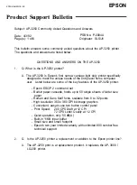
Paper wrap
With the sheet of paper clamped, the timing belts are rotated forward so the
paper is pulled completely out of the paper tray, past the paper feed guide and
the paper clamp guide and into the print path. At this point the paper clamp
guide moves up. Note how the x-axis tensioner lifts up, via cam action, out of
the way as the paper clamp bar passes underneath.
Figure 5-7. The printing cycle - paper loading
Platen
8850-18
Axis tensioner