Calibration—
7D
14
J t
Seven-Division
r
|
I
Pulse
Period
I
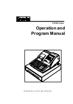
Fig. 5-1. Pulse generator output waveform for checking external
gate operation.
f.
Set the pulse generator
variable width control
for a
two-division positive-pulse width (measure
the
pulse width
where the
positive-pulse amplitude is
two divisions, as
shown
in Fig. 5-1).
g.
Disconnect
the
50-ohm
BNC termination
from the
amplifier
unit input and connect it
to the EXT GATE input
connector
through
the BSM
to
BNC female adapter.
h.
Connect the
marker
output of the time-mark
gener
ator
to
the
CH A INPUT through the 42-inch BNC cable.
i. Set
the
time-mark
generator for 2 nanosecond
markers.
j.
CHECK
—Readout
display for a count of 0100
±15
counts (0085
to 0115).
k.
Disconnect
all test equipment.
11.
Check
Manual
Gate
a.
Change the
following control settings:
7D14
DISPLAY TIME
°°
(infinite)
b.
Connect the
marker output of the
time-mark gener
ator
to
the CH
A INPUT through the 42-inch BNC cable.
50-ohm
BNC
termination,
and BNC T connector. Connect
the
output of the T connector to the amplifier
unit input
through the
18-inch BNC cable.
c. Set
the time-base unit
for a
sweep rate of two
seconds/division.
d. Set the
time-mark generator
for one-second markers.
e.
Momentarily
press
the RESET button.
f.
Press
the MANUAL GATE ON button, count
ten
time marks
on
the CRT; then press the
MANUAL GATE
OFF
button.
g.
CHECK—Readout
display for
a count of 0010 ±1
count (0009
to
0011).
h.
Disconnect
all test equipment.
12.
Check
External
Reset
a.
Set
the time-base
unit for a
sweep rate of 0.1 µs/
division.
b.
Connect
the
pulse
generator output to the amplifier
unit input
through the 42-inch
BNC cable and 50-ohm
BNC
termination.
c. Set the
pulse generator
output amplitude for a two-
division display.
d. Set
the pulse generator for a five-division positive
pulse width.
e.
Set the
pulse generator
for manual
trigger operation.
f.
Disconnect the 50-ohm
BNC termination from
the
amplifier
unit input and connect it to the
RESET pin-jack
connector
through the
pin-jack cable.
g.
Momentarily
press the
pulse generator manual trigger
button.
h.
CHECK
—Readout
display for
zero count ±1 count
(0000
to
0001).
i. Disconnect
all test equipment.
5-10
Summary of Contents for 7D14
Page 4: ...7D14 ...
Page 11: ...Operating Instructions 7D14 Fig 2 1 7D14 front panel controls and connectors 2 2 ...
Page 33: ... 3 13 Fig 3 11 Logic diagram for Zero Cancel Logic stage Circuit Description 7D14 ...
Page 38: ...3 18 Fig 3 16 Time Base and Control circuit detailed block diagram Circuit Description 7D14 ...
Page 44: ...NOTES ...
Page 46: ...NJ Fig 4 1 Electrode configuration for semiconductors in this instrument I ...
Page 68: ...NOTES ...
Page 96: ... 7DI 4 DIGITAL COUNTER UNIT ...
Page 98: ...GRS 0371 BLOCK DIAGRAM ...
Page 99: ......
Page 103: ...0 0 I 200 mV 500 µs 0 001 200 mV 500 µs 0 001 MHz 00 mV E 00 µs 0 001 MHz ...
Page 106: ...1 ...
Page 110: ...A2 Logic Circuit Board Assembly jQ798i 798 jc743 CR744t uni R724 R742 JL744S FrR796 ...
Page 113: ......
Page 114: ...P 0 A2 LOGIC BOARD ...
Page 121: ... A B D t F H J NPR Tj ZWX V A AC M AEA HUM qAZ DEF HJ N P R S T J V V7X y ABM APAI AA 7DI4 ...
Page 129: ......
Page 130: ...4 7D14 DIGITAL COUNTER ...