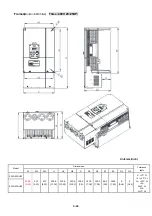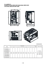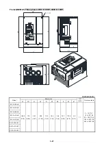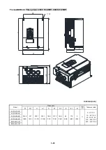
3-38
3.6.2 Control circuit terminal description
Type
Terminal
Terminal function
Signal level
S1 Forward
─
Stop (Preset), Multi function input terminal
S2 Reverse
─
Stop (Preset), Multi function input terminal
S3
Preset Speed0(5-02),Multi function input terminal
S4
Preset Speed1(5-03), Multi function input terminal
S5
Preset Speed2(5-05), Multi function input terminal
Digital
input
signal
S6
Fault reset input, Multi function input terminal
24 VDC, 8 mA, Optical
coupling
isolation(Max,voltage30 Vdc,
Input impedance 3.3k
Ω
)
R1A
NO(
Normally
open)
R1B
NC(
Normally
closed)
R1C COMMON
R2A
Relay
output
R2C
Multi function output:Run,Fault,setting
Frequency ,Frequency Reached,Auto
Restart,Momentary AC Power Loss,Rapid
Stop ,Base Block Stop Mode,Motor Overload
Protection,Drive Overload
Protection,Over-torque Threshold Level
、
Preset Current level Reached
、
Preset Brake
Frequency Reached,PID Feedback Signal
Loss
,Final count value reached, Initial count
value recahed
,PLC Status Indicator ,PLC
control…
250VAC/1A(30VDC/1A)
24V
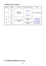
Digital signal common terminal (JP1 Switching NPN
position)
24VPower
supply
COM
Digital signal common terminal (JP1 Switching PNP position)
±15%,Max output current
60mA
10V
Built in Power for an external speed potentiometer
10V(Max current:2mA)
AI1
Multifunctional analog input available JP2 switching voltage or
current input
Voltage:JP2 Switching AVI position
Current:JP2 Switching ACI position
0 ~ 10V,(Max current:2mA)
(Input impedance: 153K
Ω
)
AI2
Multifunctional analog input available JP3 switching voltage or
current input
Voltage:JP3 cut to AVI position
Current:JP3 cut to ACI position
0 ~ 10V,0 ~20mA
(Input impedance: 153K
Ω
)
AGND
The analog common terminal
----
The
analog
input
signal
Shielding wire connecting terminal (The earth)
----
AO
Multifunctional analog output terminal*3
0 ~10V,(Max current:2mA)
The
analog
onput
signal
AGND
The analog common terminal
----
SF
Safety
switch
SG
Terminal SF is for safety switch, SF can cut off the inverter
voltage output.
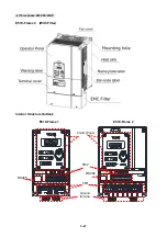
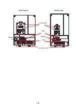
Control circuit terminal:
Summary of Contents for e510 series
Page 1: ......
Page 8: ...2 1 Chapter 2 Part Number Definition 2 1 Model Part Number...
Page 13: ...3 4 Screw M4 Screw M4...
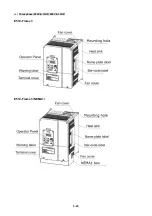
Page 34: ...3 25 c Three phase 200V 8 10HP 400V 8 15HP E510 Frame 3 E510 Frame 3 NEMA1...
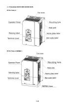
Page 35: ...3 26 d Three phase 200V 15 20HP 400V 20 25HP E510 Frame 4 E510 Frame 4 NEMA1...
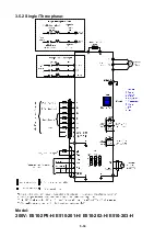
Page 43: ...3 34 3 5 2 Single Three phase Model 200V E510 2P5 H E510 201 H E510 202 H E510 203 H...
Page 197: ......


