4-41
03- 07
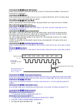
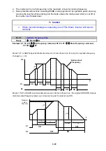
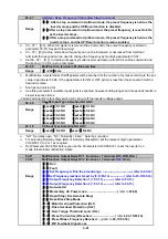
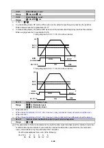
Up/Down Keep Frequency Status after Stop Command
Range
【
0
】
: After a stop command in Up/Down mode, the preset frequency is held as the
inverter stops,and the UP/Down function is disabled.
【
1
】
After a stop command in Up/Down mod, the preset frequency is reset to 0 Hz
as the inverter stops.
【
2
】
:
After a stop command in Up/Down mode
,
, the preset frequency is held as the
inverter stops, and the UP/Down function remains enabled.
¾
03 - 07 =
【
0
】
, When run signal is removed (Stop Command), the output frequency is stored in
parameter 05-01( Key pad Frequency).
¾
03 - 07 =
【
0
】
In stop mode since frequency can not be increased or decreased from Up/Down
terminals then keypad can be used to change the frequency by modifying parameter 05-01.
¾
Set 03 - 07 =
【
1
】
, In Up/down frequency mode inverter will ramp up from 0Hz on Run command and
Ramp down to 0 Hz on stop command.
03- 08
Multifunction terminals S1~S6 scan time
Range
【
1~200
】
2ms
¾
Multifunction input terminal On/Off periods will be scanned for the number of cycles according to the set
value in parameter 03-08. If the signal status for ON or OFF period is less than the set period it will be
treated as noise.
¾
Scan period unit is 2ms.
¾
Use this parameter if unstable input signal is expected, however setting long scan time periods results in
slower response times.
Note: Terminal SF is for safety switch,
※
SF can cut off the inverter voltage output.
03- 09
S1
~
S5 Input Type Selection NO & NC
Range
【
xxxx0
】
:S1 NO
【
xxxx1
】
:S1 NC
【
xxx0x
】
:S2 NO
【
xxx1x
】
:S2 NC
【
xx0xx
】
:S3 NO
【
xx1xx
】
:S3 NC
【
x0xxx
】
:S4 NO
【
x1xxx
】
:S4 NC
【
0xxxx
】
:S5 NO
【
1xxxx
】
:S5 NC
03- 10
S6 Input Type Selection NO & NC
Range
【
xxxx0
】
:S6 NO
【
xxxx1
】
:S6 NC
¾
“NO”: Normally open, “NC”: Normallly closed. . Select as required
¾
For selecting Normally Open (NO) or Normally Closed(NC) set the relevant digit in parameter
03-09/03-10 to 0 or 1 as required.
¾
Set Parameter 03-09 first before you use the Parameters 00-02/00-03=1 to set the inverter run
mode to External multifunction inputs.
03-11
Multifunction Output Relay RY 1 functions. ( Terminals R1C,R1B, R1A )
03-12
Multifunction Output Relay RY 2 functions. ( Terminals
R2C
, R2A )
Range
【
0
】
:Run
【
1
】
:Fault
【
2
】
:Set Frequency within the preset range. -------------------------------( refer to 03-14)
【
3
】
:Set Frequency reached. As set by (3-13±3-14) -------------- ( refer to 03-13/03-14)
【
4
】
:Output Frequency Detection 1 (> 03-13) ----------( refer to 03-13)
【
5
】
:Output Frequency Detection 2 (< 03-13) ----------( refer to 03-13)
【
6
】
:Auto-restart
【
7
】
:Momentary AC Power Loss
---------------------------------
(
refer to
07-00)
【
8
】
:Rapid Stop ( Decelerate to Stop)
【
9
】
:Base Block Stop Mode
【
10
】
:Motor Overload Protection (OL1)
【
11
】
:Drive Overload Protection (OL2)
【
12
】
:Over Torque Threshold Level (OL3)
【
13
】
:Preset Current level Reached
-------------------------
(
refer to
03-15/03-16)
【
14
】
:Preset Brake Frequency Reached
-----
(
refer to
03-17/03-18)
【
15
】
:PID Feedback Signal Loss
Summary of Contents for e510 series
Page 1: ......
Page 8: ...2 1 Chapter 2 Part Number Definition 2 1 Model Part Number...
Page 13: ...3 4 Screw M4 Screw M4...
Page 34: ...3 25 c Three phase 200V 8 10HP 400V 8 15HP E510 Frame 3 E510 Frame 3 NEMA1...
Page 35: ...3 26 d Three phase 200V 15 20HP 400V 20 25HP E510 Frame 4 E510 Frame 4 NEMA1...
Page 43: ...3 34 3 5 2 Single Three phase Model 200V E510 2P5 H E510 201 H E510 202 H E510 203 H...
Page 197: ......


